Author Topic: Basic zener diode operation  (Read 1410 times)

0 Members and 1 Guest are viewing this topic.

Offline joshcarrTopic starter

  • Contributor
  • Posts: 17
  • Country: us
Basic zener diode operation
« on: September 28, 2017, 03:06:30 pm »
I'm trying to make a lighting system for a motorized bicycle that runs off the magneto. There is a white wire that comes of the magneto that puts out around 4-7V depending on the rpm of the engine. I have a small 6v SLA battery that I want to put in line as a buffer/reservoir between the power straight from the magneto and the lights, which are all LEDs. If I understand correctly I should be able to put a 6v zener diode in reverse bias between the magneto and the battery and the battery will get power at 6v or more? Also is there a better way to regulate the voltage to an optimum amount for float charging the battery? For a 6v SLA I think a safe float charge is around 7v. Thanks.
 

Offline george.b

  • Frequent Contributor
  • **
  • Posts: 383
  • Country: br
Re: Basic zener diode operation
« Reply #1 on: September 29, 2017, 01:05:27 am »
If you do that, your Zener might explode. :scared:
Current will flow from the battery to the generator when at low RPM (the voltage from the generator will be lower than the battery voltage, so the Zener diode will be forward-biased), and it won't flow from the generator to the battery until the voltage from the generator is over 12V or so (probably never, then). Even then, the current handling capability of a Zener diode is probably too low for what you want.

A forward-biased rectifier diode (Schottky, preferably) is one way to do it, albeit not very efficient. When the voltage from the generator is one diode voltage drop above the battery voltage, then current will flow from the generator to the battery, and not in the opposite direction. This won't give you any regulation or overvoltage protection, but if the maximum voltage the generator puts out is 7V...

The really nice way to do this would be to use a boost, or maybe a buck-boost converter. Then the battery would get charged even when the generator is putting out a voltage lower than the battery.
 

Offline batteksystem

  • Regular Contributor
  • *
  • Posts: 167
  • Country: hk
    • My ebay store
Re: Basic zener diode operation
« Reply #2 on: September 29, 2017, 01:47:32 am »
A cheap way to do it is probably a schottky diode and a zener diode which clamp the voltage to something around 6V. Without knowing the current requirement, it is not possible to estimated how big the diodes will be, though.

Offline joshcarrTopic starter

  • Contributor
  • Posts: 17
  • Country: us
Re: Basic zener diode operation
« Reply #3 on: September 29, 2017, 02:23:49 am »
Max current would be about 3 amps. Preferably I would like to have the voltage boosted to 6v so it charges all the time. I was looking into boost converters but all I could find had to have the input voltage 2-3 volts below 6v to even work. If the generator is putting out 6v wouldn't the a boost converter set to 6v not work? Or could I put a schottky diode before the converter maybe to allow 6v to flow when the boost converter is out of its range? I may be completely wrong in how boost converters work so please correct me lol
 

Offline george.b

  • Frequent Contributor
  • **
  • Posts: 383
  • Country: br
Re: Basic zener diode operation
« Reply #4 on: September 29, 2017, 07:33:20 am »
Yeah, 3 amps is a lot of current for a Zener. I don't know of any Zener diodes that can handle it. You'd have to use it in an emitter follower circuit, like so:

That's not really a solution to your problem, though.

Well, take a look at the canonical boost converter schematic:


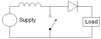
Admitting ideal components, the output voltage is 1/(1-D) times the input voltage, D being the duty cycle. As D approaches zero, Vout approaches Vin. You can see that in the schematic - when the switch stays open all the time, the input is bypassed through the diode. Ignoring its voltage drop, the output equals the input.
Now, I don't know how an off-the-shelf solution would react to being fed a voltage higher than the output, it could have protections against such a situation, but if you were to build it, it should work. What exactly have you found?

A buck-boost converter would be a more elegant solution, as it can step the voltage up or down, but since the maximum output from the generator is 7V, I don't believe it's absolutely necessary to use that topology.

Ah, by the way: magnetos output AC. Is this 4~7V output you're measuring already rectified and filtered to DC, or is it AC?
 

Offline mikerj

  • Super Contributor
  • ***
  • Posts: 3240
  • Country: gb
Re: Basic zener diode operation
« Reply #5 on: September 29, 2017, 11:32:27 am »
Unless you are doing this just for the challenge then it would be a lot easier and cheaper to buy a rectifier/regulator unit for a small motorcycle or moped.
 

Offline joshcarrTopic starter

  • Contributor
  • Posts: 17
  • Country: us
Re: Basic zener diode operation
« Reply #6 on: September 29, 2017, 06:42:46 pm »
I'd like to have an upper limit just because it's a cheap engine and spikes sometimes. 4-7v is nominal output but it can go higher sometimes and I don't want to fry any LEDs. It is AC still, not DC. I've been looking for buck boost converters but all I've found is either rated for like 1/2 a watt or not 6v.

mikerj something like this? http://www.ebay.com/itm/6v-Rectifier-Moped-Scooter-Minibike-/142487429517?_trksid=p2385738.m2548.l4275
I want the easiest solution i don't care how it's done lol


Share me

Digg  Facebook  SlashDot  Delicious  Technorati  Twitter  Google  Yahoo
Smf