Author Topic: BME280 power supply problems (How can I clean VCC ?)  (Read 4650 times)

0 Members and 1 Guest are viewing this topic.

Offline JacquesBBBTopic starter

  • Frequent Contributor
  • **
  • Posts: 829
  • Country: fr
BME280 power supply problems (How can I clean VCC ?)
« on: December 16, 2017, 10:44:26 pm »
Hello All,

I use a ESP8266 module to drive a relay using a board that has a small SMPS like this one
http://www.electrodragon.com/product/wifi-iot-relay-board-spdt-based-esp8266/.

But I encounter problems, mostly due to the power supply.

The board is connected to the main, and the SMPS provides 5 V  and 3.3V necessary for the ESP8266.
If I  power the BME280 by an external battery, everything is fine.
But If I power it on the 3.3V  rail  of the board,  I have from time to time bad measures ( spikes in the temp or humitity curve).

I have tried to use the 5V  rail, and  lower it to 3.3V using a linear AMS1117 chip,  but the spikes remain.

DO you have a good solution to solve this problem ?

I could add an intermediary  LiPo battery that would be charged by the 5V, but I am not sure it will solve the problem,
as   the  AMS1117 module did not solve it.

Thanks for any help.
« Last Edit: December 23, 2017, 11:15:08 am by JacquesBBB »
 

Offline kripton2035

  • Super Contributor
  • ***
  • Posts: 2581
  • Country: fr
    • kripton2035 schematics repository
Re: BME280 power supply problems
« Reply #1 on: December 16, 2017, 10:53:33 pm »
add some capacitor like 100µF on the vcc rail of the bme280
change the output capacitor of the ac-dc module for the same value or test also a higher value
would be nice to have a scope output of the supply and the spikes ?
 

Offline JacquesBBBTopic starter

  • Frequent Contributor
  • **
  • Posts: 829
  • Country: fr
Re: BME280 power supply problems
« Reply #2 on: December 16, 2017, 11:07:33 pm »
I have added this module

https://www.ebay.com/itm/5pcs-4-5V-7V-to-3-3V-AMS1117-3-3V-Power-Supply-Module-AMS1117-3-3/400985442255?hash=item5d5c9847cf:g:3wwAAOSwF1dUSgkD

And a 100uF capacitor on the output of the AMS1117 module, but it does not solve the problem.

For the scope view, I will have to dismount everything.
 

Offline floobydust

  • Super Contributor
  • ***
  • Posts: 6959
  • Country: ca
Re: BME280 power supply problems
« Reply #3 on: December 17, 2017, 04:41:52 am »
The electrodragon ESP-32 relay board is kind of a disaster  :palm:
The mains SMPS PC board is right on top the motherboard; The power supply is simply too close to the MCU and I/O PCB traces.
So you have several hundred volts of switching millimeters away radiating to the low voltage traces and ESP right nearby.

I would expect the ESP-32 to have poor WiFi range and anything nearby, like the BMP280 to have problems.


Offline JacquesBBBTopic starter

  • Frequent Contributor
  • **
  • Posts: 829
  • Country: fr
Re: BME280 power supply problems
« Reply #4 on: December 17, 2017, 05:14:19 am »
OK,
I thought also that the SMPS radiation was the problem.

But it is not the case. If I leave everything as it is, and just power the BME280 with a battery, everything is fine.


By the way, its ESP8266, not ESP32.
« Last Edit: December 17, 2017, 06:10:56 am by JacquesBBB »
 

Offline kripton2035

  • Super Contributor
  • ***
  • Posts: 2581
  • Country: fr
    • kripton2035 schematics repository
Re: BME280 power supply problems
« Reply #5 on: December 17, 2017, 07:25:52 am »
did you try to put the ac-dc module out of the esp module ?
 

Offline floobydust

  • Super Contributor
  • ***
  • Posts: 6959
  • Country: ca
Re: BME280 power supply problems
« Reply #6 on: December 17, 2017, 09:36:39 pm »
post pics of your build, schematic.  I don't know how long the cable is to the BME280 etc. Why 5V this is all 3.3V stuff.
The bad (temperature, pressure humidity) readings are high or low or corrupt or what is wrong?
 

Offline JacquesBBBTopic starter

  • Frequent Contributor
  • **
  • Posts: 829
  • Country: fr
Re: BME280 power supply problems
« Reply #7 on: December 18, 2017, 06:54:04 pm »
post pics of your build, schematic.  I don't know how long the cable is to the BME280 etc. Why 5V this is all 3.3V stuff.
The bad (temperature, pressure humidity) readings are high or low or corrupt or what is wrong?

The schematic is quite simple :
The electrodragon board (EB) has a connector where you can find

GND
5V
3.3V
SDA (5)
SCL (4)

The cable is 20 cm

In a first try I connected the 4 pins  to the equivalent  in the BME280

(EB)     (SME280)

GND ----  GND
3.3V ----  VCC
SDA ----   SDA
SCL  ----  SCL

I had many spikes in the readings ( wrong values as  20125 instead of 20.125  but also different errors 9556 value for example)

Then I  put an intermediary  Lipo Battery without changing the I2C cable.
everything was fine but not satisfactory as the battery will discharge.

(EB)     (BATT)  (SME280)

GND ----  (-) ------ GND
               (+) ----  VCC
SDA  --------------- SDA
SCL  --------------- SCL

I then tried to use the 5V output and regulate the power voltage with a   AMS1117 module

(EB)     (AMS1117-3.3V)       (SME280)

GND ----  (- IN)   (-OUT) ------ GND
 5V -----  (+IN)   (+OUT) -----  VCC
SDA  --------------- SDA
SCL  --------------- SCL

But it did not solve the problem, even if I added a 100uF on the input and output of the AMS1117 module .
« Last Edit: December 18, 2017, 07:03:06 pm by JacquesBBB »
 

Offline floobydust

  • Super Contributor
  • ***
  • Posts: 6959
  • Country: ca
Re: BME280 power supply problems
« Reply #8 on: December 19, 2017, 05:52:22 pm »
Many things can cause the intermittent jumbling of data. Without pics and better sch I can only guess about the problem. Some things to look at:

Ensure the BME280 has nearby decoupling caps and some filtering on Vcc (0.1uF, 10uF w/100R to Vcc) ok as part uses <1ma.

Ensure the I2C pull up resistors are 4k7 or lower. No idea what you are doing for VccIO, Vcc.
What speed are you running this at, experiment with lower or faster. It might be WiFi chirps corrupting the I2C transfers.

Your 5V SMPS is probably making a common-mode EMI problem. Measure ACV from earth-ground to circuit GND and see what you get.

What are you using for a BME280 firmware? Some library routines have a bug for multi-byte transfers where they give an extra runt clock pulse every 8 bits, so a 16-bit transfer gets the last byte corrupted intermittently.

I got temperature readings 2-3C higher, depending on the BME280 software library I use. Bosch, Adafruit, RPi, Cactus etc. I think some bugs there reading the CAL coefficients.

The sensor is sensitive to light, and humidity sensor needs conditioning after PCB wash.
 

Offline JacquesBBBTopic starter

  • Frequent Contributor
  • **
  • Posts: 829
  • Country: fr
Re: BME280 power supply problems
« Reply #9 on: December 23, 2017, 10:41:11 am »
pics :

This is the setting  with the AMS117 module
I then tried to use the 5V output and regulate the power voltage with a   AMS1117 module

(EB)     (AMS1117-3.3V)       (SME280)

GND ----  (- IN)   (-OUT) ------ GND
 5V -----  (+IN)   (+OUT) -----  VCC
SDA  --------------- SDA
SCL  --------------- SCL


The AMS117 module is this one

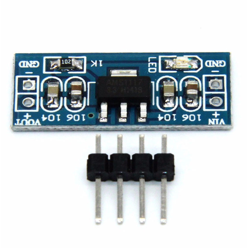
Where I added a 100 uF cap on input and output + a ferrite bead (120 R) on the plus output.


This is the setting when you do not power the BME280 by the ESP8266 board, but by an external LiPO battery
(the  data   wires SDA, SCL, are unchanged )


(EB)     (BATT)  (SME280)

GND ----  (-) ------ GND
               (+) ----  VCC
SDA  --------------- SDA
SCL  --------------- SCL

This is the BME280 with all necessary  pullup resistors (10k) and decoupling caps


-------
And finally,  this is the output


I am using  the adafruit library for the BME280 , and blynk.

As you can see,  before 18:00, which corresponds to the setting with the AMS1117,   the data is corrupted. After 18:00, when powered by the battery, everything is fine.


Ensure the BME280 has nearby decoupling caps and some filtering on Vcc (0.1uF, 10uF w/100R to Vcc) ok as part uses <1ma.

Ensure the I2C pull up resistors are 4k7 or lower. No idea what you are doing for VccIO, Vcc.
What speed are you running this at, experiment with lower or faster. It might be WiFi chirps corrupting the I2C transfers.

What are you using for a BME280 firmware? Some library routines have a bug for multi-byte transfers where they give an extra runt clock pulse every 8 bits, so a 16-bit transfer gets the last byte corrupted intermittently.

I got temperature readings 2-3C higher, depending on the BME280 software library I use. Bosch, Adafruit, RPi, Cactus etc. I think some bugs there reading the CAL coefficients.

The sensor is sensitive to light, and humidity sensor needs conditioning after PCB wash.

All these are excluded as the sensor behaves perfectly when powered by the battery, with the same data wires.

It is not either the EMI radiation from the power supply, as  the wires in the Lipo setting can as well grab these EM
radiations, and obviously do not affect the data.

The problem seems to come from the  VCC wire. If I power directly the BME280 module from the 3.3V output of the board,


(EB)     (SME280)

GND ----  GND
3.3V ----  VCC
SDA ----   SDA
SCL  ----  SCL

I have the same problem. This was my motivation from inserting the AMS1117 module. But it did not work.


« Last Edit: December 23, 2017, 11:08:34 am by JacquesBBB »
 

Offline JacquesBBBTopic starter

  • Frequent Contributor
  • **
  • Posts: 829
  • Country: fr
Re: BME280 power supply problems (How can I clean VCC ?)
« Reply #10 on: December 24, 2017, 07:02:25 pm »
I made some progress on this problem, and I  understand even less.

In order to better understand the problem, I used another relay board ( of a more recent design, but still from electrodragon http://www.electrodragon.com/product/wifi-iot-relay-board-based-esp8266/.
I then made the same setting in my workshop,
and everything was perfectly fine,  even if I powered the BME280  directly from the 3.3V of the
board.

I then switch the BME280,  suspecting that it could come from the BME280, but everything was fine.

I  then exchange the board,  putting in place the new one, and bringing back the old one to my worksop,
but now everything was fine again, even with the old board.

I  thus dont understand anything now, but as it works, will leave it like that, but be prepared for another time.
 

Offline floobydust

  • Super Contributor
  • ***
  • Posts: 6959
  • Country: ca
Re: BME280 power supply problems (How can I clean VCC ?)
« Reply #11 on: December 24, 2017, 08:43:04 pm »
My theory is the SMPS is making too much common-mode EMI for the long cable with (BME280) 10k pullups on SDA, SCL.
This will make it work/not work depending on where the circuit is running, on the bench, your hand close to the wires etc.

You can turn on pullups on the MCU I2C pins to help somewhat. A clamp-on ferrite bead on the BME cable. Earth-ground the PSU(-) and see what happens.

The LiPo is higher than 3.3V
 

Offline JacquesBBBTopic starter

  • Frequent Contributor
  • **
  • Posts: 829
  • Country: fr
Re: BME280 power supply problems (How can I clean VCC ?)
« Reply #12 on: December 24, 2017, 09:38:09 pm »
I was too optimistic.

After a  few hours without errors,  the first board ( now  on my workbench )  gives a lot  of errors.
I will thus be able to investigate more easily the sources of these errors.

@floobydust
Do you think than  changing the pullup resistors from 10 k  to 4.7k will improve  the situation ? 

I will add a ferrite bead. I did it already without much success, but I will do  it again in a more controlled environment.

In any case, it seems that the new design of the eletrodragon board has improved over the previous one;
 What I like in this board, is that it has a  full ESP-12F module, with 4 Mb memory, which allows to do
OTA programming without changing the memory chip, as in the sonoff.


« Last Edit: December 24, 2017, 09:41:09 pm by JacquesBBB »


Share me

Digg  Facebook  SlashDot  Delicious  Technorati  Twitter  Google  Yahoo
Smf