Author Topic: Cheap PWM Motor Circuit  (Read 2935 times)

0 Members and 1 Guest are viewing this topic.

Offline mribbleTopic starter

  • Regular Contributor
  • *
  • Posts: 202
Cheap PWM Motor Circuit
« on: April 19, 2017, 09:03:32 pm »
I am trying to create an inexpensive PWM Motor controlling circuit.  I want it to have a frequency of 25Khz and then there will be a potentiometer to control the duty cycle from 0 to 100%.  The motor operates at 5V and max current is under 1A.  I'm going to be building a lot of these so I wanted to keep the price as low as possible.

Initially I was going to use a 555 timer, but realized it was kind of difficult to set the 0-100% duty cycle at a constant frequency.  Then I started thinking some thinking and realized perhaps I could do what I want with a simple RC circuit (potentiometer controls duty cycle), a resonator, and comparator (lm393).

There are so many different strategies and I listed just two.  I'm wondering what high level strategy you experts would use to keep the price as low as possible?

I'm a software guy and all this is getting a bit out of my comfort zone.  In the past I'd just use a cheap 50 cent micro so I could go back to my friendly code, but in this case I want to avoid the cost of programming the micro.  If someone would be willing to help design this circuit, create a BOM, and explain its operation to me that would save me a lot of time.  I'd be happy to pay someone $100 for that.  Let me know if you're interested.
 

Offline Qmavam

  • Regular Contributor
  • *
  • Posts: 190
  • Country: us
Re: Cheap PWM Motor Circuit
« Reply #1 on: April 20, 2017, 01:55:39 am »
  This first circuit looks like what you want.
http://circuitdiagramcentre.blogspot.com/2012/07/small-dc-motor-control-using-pwm.html

There are more below, but, You can probably buy one much cheaper than you can build it.
Here's one for $4.99, You can't buy the parts for that price.
http://www.ebay.com/itm/12V-24V-Max-20A-PWM-DC-Motor-Stepless-Variable-Speed-Control-Controller-Switch-/111936836128?hash=item1a0ff49220:g:REkAAOSwcUBYU0wW
Search ebay with 'pwm dc motor controller', there are plent under $15.
Buy one, test it hard, if it good, you can probably get a much better price for 100.

https://forum.allaboutcircuits.com/threads/pwm-rgb-led-help-understanding.28586/

http://www.electroboom.com/?tag=pwm

                             Mikek
 

Offline mribbleTopic starter

  • Regular Contributor
  • *
  • Posts: 202
Re: Cheap PWM Motor Circuit
« Reply #2 on: April 20, 2017, 11:48:26 am »
I think I can do a much better price than the ebay route if I design something.  I've got a pcb manufacturer and assembler that I've used for past projects that does a great job and is really affordable for my 100s to 1000s of unit batches.

The circuit you sent is probably the best I've seen, and I have done quite a bit of searching now.  A quad op-amp in a single chip with just a few resistors/caps to generate the PWM signal that feeds into a mosfet is going to be about as low cost as I can get (or at least close enough that I no longer care).  I can certainly modify the values of the opamp to adjust the frequency of the square/triangle waves so I should be able to handle the design from this point (especially since it's so easy to breadboard this system and confirm my design).

Thanks for the great help!
 

Offline Qmavam

  • Regular Contributor
  • *
  • Posts: 190
  • Country: us
Re: Cheap PWM Motor Circuit
« Reply #3 on: April 20, 2017, 12:26:01 pm »
I think I can do a much better price than the ebay route if I design something.  I've got a pcb manufacturer and assembler that I've used for past projects that does a great job and is really affordable for my 100s to 1000s of unit batches.

 Ok, I thought you were going have a pcb made and stuff it yourself, that would kill any profit.
I'm not sure of your end use, but the case is the most costly part.
Quote
The circuit you sent is probably the best I've seen, and I have done quite a bit of searching now.  A quad op-amp in a single chip with just a few resistors/caps to generate the PWM signal that feeds into a mosfet is going to be about as low cost as I can get (or at least close enough that I no longer care).

 I built one similar, I couldn't find the page I built it from, but it worked perfectly.

[/quote]
 I can certainly modify the values of the opamp to adjust the frequency of the square/triangle waves so I should be able to handle the design from this point (especially since it's so easy to breadboard this system and confirm my design).

Thanks for the great help!
[/quote]
 

Online Zero999

  • Super Contributor
  • ***
  • Posts: 19481
  • Country: gb
  • 0999
Re: Cheap PWM Motor Circuit
« Reply #4 on: April 20, 2017, 05:18:49 pm »
I am trying to create an inexpensive PWM Motor controlling circuit.  I want it to have a frequency of 25Khz and then there will be a potentiometer to control the duty cycle from 0 to 100%.  The motor operates at 5V and max current is under 1A.  I'm going to be building a lot of these so I wanted to keep the price as low as possible.

Initially I was going to use a 555 timer, but realized it was kind of difficult to set the 0-100% duty cycle at a constant frequency.  Then I started thinking some thinking and realized perhaps I could do what I want with a simple RC circuit (potentiometer controls duty cycle), a resonator, and comparator (lm393).

There are so many different strategies and I listed just two.  I'm wondering what high level strategy you experts would use to keep the price as low as possible?

I'm a software guy and all this is getting a bit out of my comfort zone.  In the past I'd just use a cheap 50 cent micro so I could go back to my friendly code, but in this case I want to avoid the cost of programming the micro.  If someone would be willing to help design this circuit, create a BOM, and explain its operation to me that would save me a lot of time.  I'd be happy to pay someone $100 for that.  Let me know if you're interested.

Actually an MCU works out more expensive for this, especially in large quantities. The only time it will be cheaper is if you want to dispense with the potentiometer and use push-buttons and or a capacitive touch sensor but most people find potentiometers more user friendly.

A 555 timer can get very close to 0% to 100%. The frequency will remain fairly constant, irrespective of the pot setting. I haven't worked out the frequency of any of the circuits below (by the way you'll need to be logged on to the forum to see them) but it doesn't change much, as the pot is adjusted.

This circuit does it quite well and if you use Schottky diodes, it'll be even better.


Another option is CMOS gates which are often cheaper than the 555 timer, use less power and will be able to get closer to 100% duty cycle. Again, use Schottkly diodes, rather than silicon. The unused gates can be connected in parallel used as a buffer to help drive a MOSFET.


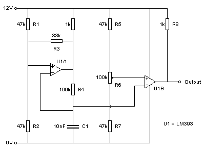
Then there's the LM393 comparator which will go from 0% to 100% duty. It has an open collector output which means it needs a pull-up resistor and it might struggle to drive a MOSFET directly at 25KHz, especially at very low/high duty cycles, so an external driver may be necessary.


It's been discussed in the following thread:
https://www.eevblog.com/forum/projects/pwm-signal-from-555-timer
 

Offline julian1

  • Frequent Contributor
  • **
  • Posts: 731
  • Country: au
Re: Cheap PWM Motor Circuit
« Reply #5 on: April 21, 2017, 02:34:22 am »


Share me

Digg  Facebook  SlashDot  Delicious  Technorati  Twitter  Google  Yahoo
Smf