Author Topic: Circuit to determine whether vehicle is running based on battery voltage level  (Read 3933 times)

0 Members and 1 Guest are viewing this topic.

Offline HwAoRrDkTopic starter

  • Super Contributor
  • ***
  • Posts: 1449
  • Country: gb
I am thinking of implementing an idea I had for something connected to a vehicle's OBD port. It will be powered by the +12V supply on the OBD port, which is usually a permanent non-switched feed direct from the battery. However, my device will only need to function when the vehicle's engine is running, so it should remain in a standby/sleep state at all other times. So, because there are no explicit means of determining 'on' state on the OBD port (no ignition-switched power feed, for example), I thought I could probably look at the voltage level to determine if the engine is running.

When 'off', the voltage will just be whatever the state of charge the battery is at - e.g. 12.x volts (or less). When 'on' and engine running, the alternator will be charging the battery, so the voltage level should be higher - probably at least 13V. Sounds right?

I think a comparator circuit should so the trick, especially as what I want out of it is a simple logic-level signal to feed to a microcontroller to tell it to either wake up or sleep.

I came up with the following circuit:
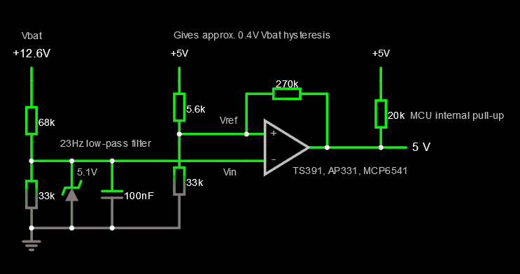


The salient points:

- Inverting arrangement; active-low output signal.
- Vbat gets divided such that approx. 13V is turned into 4.3V, plus low-pass filtered to avoid errant transients.
- A 5.1V zener protects the inverting input of the comparator should Vbat go any higher than expected.
- Vref is fed from +5V VCC, divided to about 4.3V. Feedback gives some hysteresis, of about 0.4V on Vbat.
- Output will use internal pull-up on connected MCU pin to ensure a defined high level when comparator is not triggered.

How does it look? Is there anything I have missed, or any way I could improve it?

Specifically, one query I have is if the input is low-pass filtered (and thus slow to rise/fall), is there any point in implementing any hysteresis? As the output is feeding an interrupt on the MCU, I suppose it is best to ensure no spurious oscillation, but I can't help wondering if I can get away without it.

Another thing I am concerned with is current draw, as this circuit will be always-on. I think it should be low power, as the simulation suggests that no more than a few hundred microamps will be drawn, but the sim gives no scope to measure current drawn by the comparator itself. What will be the current draw of a single-channel comparator?

For choice of comparator, I have been looking for something ubiquitous and cheap in a SOT package - the noted part nos. (TS391, AP331, MCP6541) are ones I've found so far. Will they be suitable?

By the way, I should probably mention that while my chosen MCU (AVR) actually features a built-in analog comparator peripheral, I cannot use it because disappointingly it does not appear to support waking up from standby/sleep modes upon a comparator interrupt, so I'll have to use an external circuit. :(
 

Offline t1d

  • Super Contributor
  • ***
  • Posts: 1211
  • Country: us
I am noobish, myself, but here are some points...
- Alternators often put out 14.4 volts, with higher spikes.
- Automobile power is very dirty. Much cleaning and protection will be needed. My guess is that your power supply circuit is not sufficient, in this regard.
- Why does the controller need to sleep, as opposed to turning off. If it can shutdown, completely, you could just power it from the ignition, or auxiliary port/cigarette lighter/etc. If the controller needs to retain settings, maybe add some non-volatile memory. Or, add its own button battery...
- If the controller is a Microchip brand unit, yes, the built-in comparator is very likely not available, for external use. I have already researched that, myself.
« Last Edit: October 18, 2018, 04:18:39 am by t1d »
 

Online tautech

  • Super Contributor
  • ***
  • Posts: 28061
  • Country: nz
  • Taupaki Technologies Ltd. Siglent Distributor NZ.
    • Taupaki Technologies Ltd.
Why not use something where the work is already done.......alternator light.
Illuminated = High = engine not running.
Extinguished = Low = engine running.
Avid Rabid Hobbyist
Siglent Youtube channel: https://www.youtube.com/@SiglentVideo/videos
 

Offline CJay

  • Super Contributor
  • ***
  • Posts: 4137
  • Country: gb
If you have access to OBD then why not let the OBD port tell you the engine is running? The data stream contains all the information you need.
 

Offline Benta

  • Super Contributor
  • ***
  • Posts: 5817
  • Country: de
Depends whether it's OBD II or 'just' OBD. OBD II is standardized, but OBD could be anything.
 

Offline HwAoRrDkTopic starter

  • Super Contributor
  • ***
  • Posts: 1449
  • Country: gb
I've just thought, I'm not sure why I used 4.3V as the reference voltage. Perhaps because I started with 15V Vbat being the 'maximum' to correspond to 5V, I dunno. I should probably make it 2.5V, smack dab in the middle of VCC range, so I'm not straying anywhere near input limits/offsets of the comparator.

Another question: would a circuit like this be fairly temperature stable? I don't think I need anything terribly precise, but I don't want to end up with a situation where, for example, cold weather renders it unable to function properly. For the Vref, would I be better off using a zener diode or perhaps a dedicated part like a TL431?


- Why does the controller need to sleep, as opposed to turning off. If it can shutdown, completely, you could just power it from the ignition, or auxiliary port/cigarette lighter/etc.

I want this device to interface solely with the OBD port, with no other wiring needed elsewhere, so the likes of aux/lighter sockets are out. As I said previously, standard OBD-II ports only feature a permanent (non-ignition-switched) power feed, so unless there's really no alternative, I want to try and work with what I've got.

Why not use something where the work is already done.......alternator light.
Illuminated = High = engine not running.
Extinguished = Low = engine running.

Because this is aimed at a range of modern vehicles that a) don't have discrete, accessible circuitry for individual warning lights (i.e. digital dash), and b) don't even have an alternator warning light anyway. :P ;D

If you have access to OBD then why not let the OBD port tell you the engine is running? The data stream contains all the information you need.

I did think of somehow using the CAN bus to determine when to wake-up or sleep, but concluded it wasn't a great idea. Yes, I could program the CAN controller on my MCU to wake up on RX of any CAN messages, but that would be added code complication, and I couldn't really use presence/absence of bus traffic to determine when to sleep - in the situation where the engine is turned off but the key is still on, all vehicle systems are still live and talking, but, because the engine is not running it would be pointless for my device to be awake.
 

Offline maginnovision

  • Super Contributor
  • ***
  • Posts: 1963
  • Country: us
You need to consider vehicles shutting the alternator off for economy reasons.  A lot of Hondas since the 90's do this. Some BMW's do it at times, and I would bet others do it too.
 
The following users thanked this post: oPossum

Offline SeanB

  • Super Contributor
  • ***
  • Posts: 16265
  • Country: za
Simplest method is just to put the input voltage through a capacitor and amplify it a lot, then use a simple window envelope detector to get the value of the noise on the supply. low noise means battery power, and high noise means engine and other loads are running, so you can simply wake up the MCU using an interrupt and it can then do the testing to see if the bus is active, then after low noise for a time go back to sleep.  Random events might wake it, but it will still time out again as if the ignition is off.
 

Offline Gyro

  • Super Contributor
  • ***
  • Posts: 9392
  • Country: gb
You need to consider vehicles shutting the alternator off for economy reasons.  A lot of Hondas since the 90's do this. Some BMW's do it at times, and I would bet others do it too.

Agreed, many cars manufactured in the past 10 years shut down the alternator when the engine is at idle, [Edit: at least while the battery has a 'safe' level of charge].
« Last Edit: October 18, 2018, 06:41:47 pm by Gyro »
Best Regards, Chris

"Victor Meldrew, the Crimson Avenger!"
 

Offline CJay

  • Super Contributor
  • ***
  • Posts: 4137
  • Country: gb
If you have access to OBD then why not let the OBD port tell you the engine is running? The data stream contains all the information you need.

I did think of somehow using the CAN bus to determine when to wake-up or sleep, but concluded it wasn't a great idea. Yes, I could program the CAN controller on my MCU to wake up on RX of any CAN messages, but that would be added code complication, and I couldn't really use presence/absence of bus traffic to determine when to sleep - in the situation where the engine is turned off but the key is still on, all vehicle systems are still live and talking, but, because the engine is not running it would be pointless for my device to be awake.

Well to be fair the presence of bus traffic wouldn't determine if the vehicle was running or not, as you say, it just tells you the ignition 'key' is on, you'd need to extract that data from the traffic to be certain.

If you need to determine if the engine is running then you may be successful trying to detect the alternator phase ripple from the 12V line as that will *only* be present if the engine is turning, if it's a petrol or diesel with EFI then injector pulses may well be detectable and give you measurable RPM, for both you'd have to consider running your device for the timeout period of the stop/start eco systems before going into standby.

I really think the best way is to extract the OBD2 data.
 

Offline Nusa

  • Super Contributor
  • ***
  • Posts: 2416
  • Country: us
You could probably tune the input resistor to an optocoupler such that it only triggers above your specified voltage. You get your signal and signal isolation in the same step.

Previous comments about alternator activity being a valid indicator of engine status apply, of course.
 

Offline spec

  • Frequent Contributor
  • **
  • Posts: 833
  • Country: england
  • MALE
+ HwAoRrDk  interesting requirement and a good solution.

Presumably you need to turn the MCU off only to save power.

You asked if there were any suggestions for improvements. These are my thoughts:

Suggest that you take a look at comparator chips with built-in hysteresis (like the MCP6541 that you mentioned) and a built in voltage reference. That way you will improve accuracy, reduce component count, and potentially minimize power consumption. One of the LT6703 family looks ideal for your application. All you would need would be the chip, two resistors and one integrating/filter capacitor.

Below is a list of comparators with built-in voltage references for you to consider.

To get around the problem of the alternator being turned off while the engine is running, would it be acceptable to have the MCU stay on, by software control, for a fairly long time after the comparator detects a no-charge battery voltage?


« Last Edit: October 20, 2018, 09:33:15 am by spec »
 

Offline HwAoRrDkTopic starter

  • Super Contributor
  • ***
  • Posts: 1449
  • Country: gb
You need to consider vehicles shutting the alternator off for economy reasons.  A lot of Hondas since the 90's do this. Some BMW's do it at times, and I would bet others do it too.

Agreed, many cars manufactured in the past 10 years shut down the alternator when the engine is at idle, [Edit: at least while the battery has a 'safe' level of charge].

Ah, I hadn't thought of that possibility. Thanks for pointing that out.

To get around the problem of the alternator being turned off while the engine is running, would it be acceptable to have the MCU stay on, by software control, for a fairly long time after the comparator detects a no-charge battery voltage?

Yes, I suppose I could do that. It should be acceptable to have my device 'on' for a while even though the engine's not running, it just won't have anything particular to do. I've no idea what would be a good 'time-out' period before sleeping, though. How long is a vehicle going to spend running with the alternator shut off? 5, 10, 30 minutes, an hour? :-//

Suggest that you take a look at comparator chips with built-in hysteresis (like the MCP6541 that you mentioned) and a built in voltage reference. That way you will improve accuracy, reduce component count, and potentially minimize power consumption. One of the LT6703 family looks ideal for your application. All you would need would be the chip, two resistors and one integrating/filter capacitor.

Neat, that looks like a very nice chip. But... oof, how much? :o Very expensive, although I don't know why I'm surprised, it's Linear. ;D

You could probably tune the input resistor to an optocoupler such that it only triggers above your specified voltage. You get your signal and signal isolation in the same step.

So you mean configure a voltage divider on Vbat so that the threshold level (13V) produces a voltage equal to the forward voltage of the optocoupler's LED? Interesting idea, although won't the Vf be fairly variable from one part to the next? A quick look at the first optocoupler datasheet I had to hand (FOD817) specifies typical of 1.2V up to a max of 1.4V. I suspect such a solution would need to be individually adjusted by a trimmer pot on the divider on a unit-by-unit basis, which isn't appealing.
 

Offline HwAoRrDkTopic starter

  • Super Contributor
  • ***
  • Posts: 1449
  • Country: gb
A thought I just had about an alternative approach: could there perhaps be some way of using the CAN bus? I don't mean data-wise, but electrically.

I recall when looking at CAN transceivers for a previous project a while back, that there were ones with some sort of 'wake up' functionality - for example, the NXP TJA1042. Datasheet says that when set in standby mode, if the transceiver detects CAN bus traffic, it pulls the RXD pin low to signal a wake-up condition.

Perhaps, I could connect the transceiver STB pin to an I/O on the MCU, together with an external pull-up resistor. When asleep (and by default at power-on) that micro pin would be set as an input, and thus floating, so the pull-up will bring STB high, putting the transceiver in standby mode. A pin-change interrupt could be set on the micro's RXCAN pin to wake it up upon RXD going low. At wake-up, the STB line would be changed to an output with low state, bringing the transceiver out of standby, and the RXCAN interrupt disabled.

Does that sound workable, or am I mis-interpreting the CAN transceiver datasheets?

This would of course not be a solution for recognising when to sleep, but I could probably just look at CAN bus data to determine when to do that (e.g. engine RPM has been zero for a certain period).
 

Offline spec

  • Frequent Contributor
  • **
  • Posts: 833
  • Country: england
  • MALE
Suggest that you take a look at comparator chips with built-in hysteresis (like the MCP6541 that you mentioned) and a built in voltage reference. That way you will improve accuracy, reduce component count, and potentially minimize power consumption. One of the LT6703 family looks ideal for your application. All you would need would be the chip, two resistors and one integrating/filter capacitor.

Neat, that looks like a very nice chip. But... oof, how much? :o Very expensive, although I don't know why I'm surprised, it's Linear. ;D

LT6703 chips are around £1.80 in one of quantities from Digikey and Mouser- is that expensive to you?
 

Offline HwAoRrDkTopic starter

  • Super Contributor
  • ***
  • Posts: 1449
  • Country: gb
LT6703 chips are around £1.80 in one of quantities from Digikey and Mouser- is that expensive to you?

Well, I only took a quick look at Farnell and RS - both had prices of £3 in single quantities for SOT23 version.

But anyway, even at the lower price it's expensive compared to a jelly-bean £0.22 comparator. ^-^
 

Offline spec

  • Frequent Contributor
  • **
  • Posts: 833
  • Country: england
  • MALE
Digikey UK have:

Microchip MCP65R41T-240 for 33p + VAT
and
Microchip MIC841 for 44p + VAT

Digikey UK also have quite a few other comparators with reference voltages for under £1
 

Offline IDEngineer

  • Super Contributor
  • ***
  • Posts: 1923
  • Country: us
I'll cast another vote for simply reading the CAN bus, specifically the ECU's RPM parameter. Everything else will be some sort of guesswork, potentially compromised by the battery's state of charge, whether the alternator is switched, yadda yadda yadda.

I've done a lot of CAN work. The presence/absence of CAN data is not a reliable indicator of "engine running", even if you filter for the ECU's source address. For example, many marine engine ECU's continue to transmit CAN data for ~30 seconds after the engine is turned off. However, that data is accurate - specifically, the RPM parameter is zero. The absence of that parameter on the CAN network, or it being zero, is authoritative that the engine is not running.

I'd argue that this is the best way to truly know if the engine is actually running. While my work has been in the marine industry, we know the parameters for OBD are quite standardized so it should be straightforward to find the RPM info. CAN PHY chips are cheap, and there are lots of MCU's with an integrated CAN interface module (the logic side), so you could accomplish the mission with low cost and low parts count.

And who knows - once you have access to the CAN data, perhaps additional cool features will become possible for your project....  :-+
 

Offline Adam60

  • Regular Contributor
  • *
  • Posts: 79
  • Country: ca
Would taking a signal from the crankshaft position sensor work? Engine signal would be digital and you would need to find a way to have a minimum to indicate it is running as opposed to cranking. I wouldn't mess with the CANBUS signal unless you really know what you are doing. It will get messy quickly. CKP is a sure sign of engine running.


Share me

Digg  Facebook  SlashDot  Delicious  Technorati  Twitter  Google  Yahoo
Smf