Author Topic: DC to DC converter  (Read 6984 times)

0 Members and 1 Guest are viewing this topic.

Offline hotterTopic starter

  • Newbie
  • Posts: 9
  • Country: lt
DC to DC converter
« on: April 03, 2014, 07:02:36 pm »
Hi, I am making DC to DC converter Vin 2.7-4.2V, Vout 1.25V by this schema:

I attach multimeter to the Vout and I get constantly changing voltage from 1.25V to 1.32V is that how it should work? shouldnt there always be 1.25V?
Also, how efficiant is this converter? I am planing to use it in the wireless mouse to power it by Liion battery and wondering how long it will last.
 

Offline mariush

  • Super Contributor
  • ***
  • Posts: 5015
  • Country: ro
  • .
Re: DC to DC converter
« Reply #1 on: April 03, 2014, 07:28:06 pm »
MC34063 needs a minimum of 3v to run.  Some may work from about 2.7v. So be careful with that.
The regulator will have some voltage ripple on the output without a load on it. As you apply some load, the ripple should decrease.

I don't see the need of having two 22uF capacitors on the output.

Measure the current used by your mouse when working (put the meter on the mA range and put it in series with the battery - use some  tape to put a wire on the negative side of the battery and the other wire to the negative terminal in the mouse and connect the multimeter probes to the wires) ... then select the inductor to work best with the current consumption of your mouse.
For example, for 10mA of current, you'll need about 450 uH.  If your mouse averages 50mA you only need 100uH... your inductor choice is more geared towards around 200mA (and I doubt your mouse used that much)

See these two online calculator : http://www.nomad.ee/micros/mc34063a/ and http://dics.voicecontrol.ro/tutorials/mc34063/  and there's even an application on sourceforge: http://sourceforge.net/projects/mc34063uc/


Offline T3sl4co1l

  • Super Contributor
  • ***
  • Posts: 21657
  • Country: us
  • Expert, Analog Electronics, PCB Layout, EMC
    • Seven Transistor Labs
Re: DC to DC converter
« Reply #2 on: April 03, 2014, 08:00:41 pm »
It's a pretty awful chip to use, in general.  Let alone at low voltages.  Pick up a proper device, one that was designed since, you know, 1970 or so (I'm not even kidding... I don't actually know when that chip was made, but it's damn old and crappy either way).

Tim
Seven Transistor Labs, LLC
Electronic design, from concept to prototype.
Bringing a project to life?  Send me a message!
 

Offline mariush

  • Super Contributor
  • ***
  • Posts: 5015
  • Country: ro
  • .
Re: DC to DC converter
« Reply #3 on: April 03, 2014, 08:35:05 pm »
I agree.

Personally, for such a project I'd probably use LTC3406ES5-1.5 : http://uk.farnell.com/linear-technology/ltc3406es5-1-5-trmpbf/reg-600ma-1-5mhz-1-5v-tsot23-5/dp/1663898

It's a fixed 1.5v buck regulator - yes it's more than 1.25v but then again that mouse is designed to accept alkaline and rechargeable batteries, so it should work with 1.25-1.6v just fine.
It's a bit expensive but on the upside, it has up to 96% efficiency, it doesn't need a diode , and as it runs at 1.5 mhz you can use a very small inductor.

2 ceramic capacitors, a surface mount inductor and you have yourself a 1.5v regulator. 

There's also LM3671MF-1.2/NOPB which is cheaper (about 50 cents), but outputs 1.2v which may be a bit too low : http://uk.farnell.com/texas-instruments/lm3671mf-1-2-nopb/ic-dc-dc-converter/dp/1685653


Offline hotterTopic starter

  • Newbie
  • Posts: 9
  • Country: lt
Re: DC to DC converter
« Reply #4 on: April 03, 2014, 08:58:52 pm »
Thank you for great suggestions. I found "LM3671MF-1.5" so that would be perfect. But I don't know if I will manage to make a schema for it. The schema in the first post isn't created by me I took it from http://jumperone.com/2011/06/convert-mouse-to-use-li-pol-batteries/ here. Also I want to add MAX1555 charger schema like in that project, do you think LM3671MF-1.5 + MAX1555 will be ok? I will try to make schema for it as I understand, if you will be able to confirm my schema that would be great.
Also "LM3671MF-1.5" is less efficient than "LTC3406ES5-1.5"?
« Last Edit: April 03, 2014, 09:03:30 pm by hotter »
 

Offline mariush

  • Super Contributor
  • ***
  • Posts: 5015
  • Country: ro
  • .
Re: DC to DC converter
« Reply #5 on: April 03, 2014, 09:57:49 pm »
The schematic is in the datasheet:  http://www.farnell.com/datasheets/1781731.pdf

LM3671MF-1.5 has built in resistors to set the voltage and everything else that would be needed otherwise - it's factory set to 1.5v. So the circuit is really simple : one capacitor at the input and output, and one inductor. Easy.


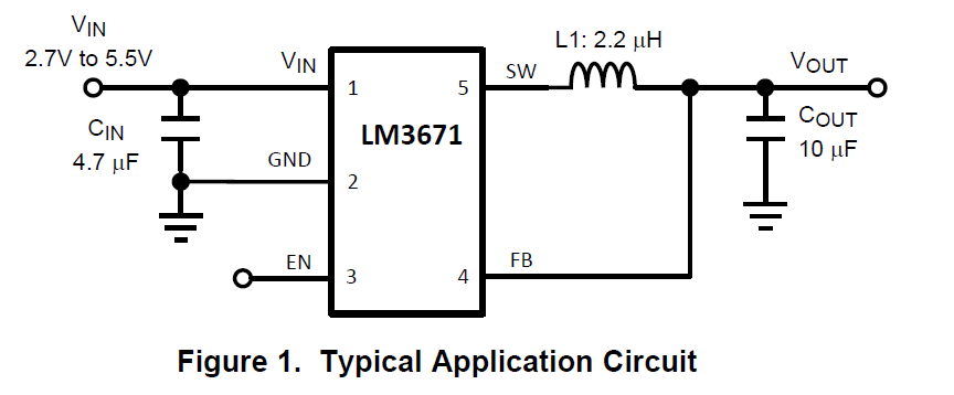
Connect EN to input voltage to get the chip to run. Keep in mind that you need to use ceramic capacitors, not electrolytics. At the high frequency this regulator works, electrolytics are no good.

later edit: Oh yes.. the inductors matters, a lot. You can't pick any 2.2uH inductor. Read the datasheet, it gives tips regarding what to use and how to pick. Basically, the inductor needs to have a low resistance (less than 0.3 ohm) and other parameters. There's also a table on page 21 that recommends some inductors - you can check the specifications of those and find something with similar specifications if those in the table are no longer available.
For example something like these should work : http://uk.farnell.com/murata/lqh43pn2r2m26l/inductor-power-2-2uh-20/dp/2219282  or http://uk.farnell.com/bourns/cvh252009-2r2m/inductor-power-20-2-2uh/dp/2118124

You can probably connect the input of the regulator it straight to the battery, the max1555 should have no problems charging the battery while this regulator takes out energy from the battery.

even later edit:  In response to: Also "LM3671MF-1.5" is less efficient than "LTC3406ES5-1.5"?

It seems to be a bit less efficient than the one I mentioned, but it's really hard to say ... the efficiency will vary with the difference between the input and output voltage.  Either way, the efficiency of both these chips can go to about 90-95%, while that mc34063 is really bad at around 65-70% efficiency.  So no matter which one you use, they're both much better.
« Last Edit: April 03, 2014, 10:11:56 pm by mariush »
 

Offline ovnr

  • Frequent Contributor
  • **
  • Posts: 658
  • Country: no
  • Lurker
Re: DC to DC converter
« Reply #6 on: April 03, 2014, 10:51:29 pm »
Actually, I recently did a lithium to alkaline regulator - this one with a special feature in that it drops the output voltage a bit (1.5V to 1.1V) to trigger the low battery alert when the lithium starts getting low, as opposed to just cutting out.

It works fairly well, but ended up being unusable for the target device due to noise (it operates in PFM mode at low currents, and the ripple didn't get along well with some sensitive analog circuitry). It's got a beautifully low quiescent consumption tho - just around 5 microamps.

Here's a (less than ideal) picture - the copper wires are just for testing. Also, bit of a bodge on a resistor there.


The board is 19mm wide, 10mm tall and around 3mm thick (incl. components). Total BOM cost (not including PCB) is $13 in one-off quantity from Digikey. If you want the design files, let me know - I'll even send you a board or two if you cover shipping.
 

Online IanB

  • Super Contributor
  • ***
  • Posts: 11858
  • Country: us
Re: DC to DC converter
« Reply #7 on: April 03, 2014, 11:07:39 pm »
I am planing to use it in the wireless mouse to power it by Liion battery and wondering how long it will last.

I power my wireless mouses with rechargeable batteries (Eneloops). It is simple, inexpensive, reliable and practical.
 

Offline hotterTopic starter

  • Newbie
  • Posts: 9
  • Country: lt
Re: DC to DC converter
« Reply #8 on: April 04, 2014, 07:16:43 pm »
Thanks vary much for the help and the advice about the inductor and capacitors, I would have bought the bad ones... The only bad thing about these chips is that they aren't in the store near me and I will need to wait two week or so for shipping, but that's worth it.
 

Offline Fank1

  • Regular Contributor
  • *
  • Posts: 159
Re: DC to DC converter
« Reply #9 on: April 04, 2014, 09:37:51 pm »
Before you quit on this one, make sure you have a minimal load on it when you test it.
 

Offline hotterTopic starter

  • Newbie
  • Posts: 9
  • Country: lt
Re: DC to DC converter
« Reply #10 on: April 20, 2014, 10:24:05 am »
So I did it, though it was not that easy to fit phones battery in to the mouse, including mini USB and circuit... I used LM3671MF-1.2/NOPB, mouse seems to work ok with 1.2V.
http://s28.postimg.org/ainona9i5/image.jpg
http://s28.postimg.org/4izxjmopp/image.jpg
http://s28.postimg.org/kiil36krh/image.jpg
But I have strange thing with MAX1555. When I connect usb the charging LED indicator goes on and off instantly it is even hard to see that. As I understand that means that the battery is not charging, because LED is off. Battery shows 4.13V. Is that how it should be? Does this mean I have the fully charged battery? Or does it mean that charging can not be done while DC to DC converter is working?
My schema:
 

Offline SeanB

  • Super Contributor
  • ***
  • Posts: 16276
  • Country: za
Re: DC to DC converter
« Reply #11 on: April 20, 2014, 11:55:34 am »
Chg low means it is not current limiting to the battery, but it is now being float charged to full. It only comes on if the charge current is over 50mA, and probably your cell is so small in capacity that it charges fast with the 50mA and then goes to flot charging.
 

Offline Witention

  • Contributor
  • Posts: 10
  • Country: 00
Re: DC to DC converter
« Reply #12 on: April 28, 2014, 10:00:56 am »
I was thinking to build one dc-dc boost converter becous i need 24V and 2A for my load(the load is solder iron heater) so can some one tell me is it wise to build dc-dc for only a heater and, the reason i want to do it is i dont have 24V and 2A rated transformer, i have 12V 0.5A, and will this 12V transformer be good for that dc-dc

Offline mariush

  • Super Contributor
  • ***
  • Posts: 5015
  • Country: ro
  • .
Re: DC to DC converter
« Reply #13 on: April 28, 2014, 12:31:21 pm »
Well, use your brains man.

If you have a 12v 0.5A transformer, that means the transformer is only capable of providing 12x0.5 = 6 watts of power.

A boost regulator won't produce those 24v out of thin air, it just converts 12v 0.5a to 24v and some current, with about 80% efficiency.  So only about 5w would be converted to 24v, the other watt is lost to efficiency, becomes heat... and so the current would be 5w / 24v = 0.2A
Your heating element needs at least 1-2A to heat up fast enough.

In addition, most heating elements run on AC power, while a boost regulator will give DC power.

You can't beat physics.


Share me

Digg  Facebook  SlashDot  Delicious  Technorati  Twitter  Google  Yahoo
Smf