Author Topic: Designing my first power supply, could use some help.  (Read 6122 times)

0 Members and 1 Guest are viewing this topic.

Offline RefrigeratorTopic starter

  • Super Contributor
  • ***
  • Posts: 1541
  • Country: lt
Designing my first power supply, could use some help.
« on: August 06, 2014, 09:03:34 am »
Hello.
I've recently made an audio amp, I wanted to test it but it seems like my wall adaptor ( with a voltage selector ) is just too weak, old and noisy, so i've thought it would be about time to make my first power supply.
At first i thought about using LM317 to make a simple variable power supply but i need quite a few amps and LM317 would just burn up, i thought about hooking them up in parallel but i think there should be an easier way to do it, i'm trying to make it from what i already got, without the need to buy anything ( shipping takes forever ). After looking for something that would be reasonably simple i've found one example and using it as a reference I made a little schematic.
PS: the numbers listed next to the bridge rectifier are AC voltages my transformer can produce.

Power transistors i'm thinking to use:
http://alltransistors.com/transistor.php?transistor=39463
I'm not sure if this would work.
Thanks in advance.
« Last Edit: August 07, 2014, 11:02:56 am by Refrigerator »
I have a blog at http://brimmingideas.blogspot.com/ . Now less empty than ever before !
An expert of making MOSFETs explode.
 

Offline mij59

  • Frequent Contributor
  • **
  • Posts: 693
  • Country: nl
Re: Designing my first power supply.
« Reply #1 on: August 06, 2014, 09:38:15 am »
Hi,

Take a look at the data sheet of the LM317 with examples how to improve your design.

http://www.ti.com/lit/ds/symlink/lm117.pdf] [url]http://www.ti.com/lit/ds/symlink/lm117.pdf[/url]

Properties to improve: load regulation
                                    load sharing between the two transistors

What output current is required ?
 

Offline RefrigeratorTopic starter

  • Super Contributor
  • ***
  • Posts: 1541
  • Country: lt
Re: Designing my first power supply.
« Reply #2 on: August 06, 2014, 09:52:02 am »
I'm thinking of about 4 ( at lower voltages ) amps and about 30 volts  ( max ) or so, i'll have to see if my transformer can handle it.
Also here's a photo of the transformer.
KT872A for size reference.
« Last Edit: August 06, 2014, 10:18:54 am by Refrigerator »
I have a blog at http://brimmingideas.blogspot.com/ . Now less empty than ever before !
An expert of making MOSFETs explode.
 

Offline RefrigeratorTopic starter

  • Super Contributor
  • ***
  • Posts: 1541
  • Country: lt
Re: Designing my first power supply.
« Reply #3 on: August 06, 2014, 09:38:32 pm »
I've made a few prototypes with the first schematic and they seemed to work OK, the only problem is that i don't have a nice big 5K pot, only a tiny pcb mount one, so there's no way of putting a knob on it. I only have 20K and 50K pots so i've thought of using an OpAmp.
The opamp i chose is NJM4556A which would use a LM7805 as a voltage reference. I'm sure this Opamp can make the two transistors work without much hesitation. From my calculations i need the max of 1.3 gain on the opamp.
D2 will most likely be a W574 Zener diode ( can be something else ).
Now i'm a bit stuck with the two potentiometers ( R2 and R3 ), i also think that R2 should be put on the other side of R3.


I would like to know if i'm going to the right direction and if i need to change, add or remove anything from the schematic.
Edit:
After some more playing around on the bread board i've decided do this without the opamp. Been thinking about stuff, making calculations, and finaly after a couple of hours of tracing came up with this masterpiece.

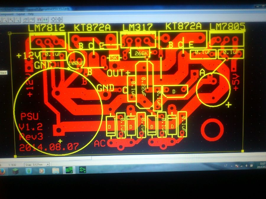
i chose to add fixed 12V and 5V rails just for the sake of it. From what i tested the output on this supply configuration, output voltage changes at about 0.01 V for every 1.5V on the AC input. The KT872A transistor seems to have a pretty low gain ( about 1.2 ) so my calculations on the opamp part were a complete nonsense. And with this configuration i should get about 0-35 V output.
I think it should work. Connections A, B and C are going to the pot on the front panel, GND is common for every output, although there is a separate ground pad and +12V pad for the internal fan ( small 1.3W one ) which can move just enough air and is pretty quiet ( no thermal speed controller BS required ).
I'll take a look at the layout one more time tomorrow and make the PCB and assemble it, i hope it doesn't go boom. :-BROKE
« Last Edit: August 07, 2014, 09:05:52 pm by Refrigerator »
I have a blog at http://brimmingideas.blogspot.com/ . Now less empty than ever before !
An expert of making MOSFETs explode.
 

Offline RefrigeratorTopic starter

  • Super Contributor
  • ***
  • Posts: 1541
  • Country: lt
Re: Designing my first power supply, could use some help.
« Reply #4 on: August 08, 2014, 11:13:58 pm »
Well, i made the board ( with a couple of changes ) and put all the parts on, soldered it all together and shortly after pluggin it in saw the magic smoke  :-BROKE and pulled the plug ASAP, it seems like the LM7812 fried, and the LM317 got pretty hot too. Honestly, i didn't expect them to pop since the LM7805 handled the voltage, gave me a nice 5V output and stayed ice cold. So i layed out another board, a little bit bigger,  much better layout that the first prototype and used only one ( but long ) jumper. I used the other tap on the transformer and got 28V DC out of it, heat shouldn't be a problem since it will be all  cooled vith a fan. And used the other tap which gave me 45V DC and put it to the power transistors. This whole thing has a common ground.

The three LM78XX regulator GND pins will be connected via the heatsink that they will be mounted on. The bigger diode rectifier will also be mounted on a heatsink. Pads with POT1, 2, 3 next to them will go to the voltage adjustment potentiometer. I put the values on every single part because i don't have a schematic for this particular design.

Feel free to criticize my design.
« Last Edit: August 08, 2014, 11:19:45 pm by Refrigerator »
I have a blog at http://brimmingideas.blogspot.com/ . Now less empty than ever before !
An expert of making MOSFETs explode.
 

Offline asgard20032

  • Regular Contributor
  • *
  • Posts: 184
Re: Designing my first power supply, could use some help.
« Reply #5 on: August 09, 2014, 04:50:04 am »
What software are you using for your schematic and pcb layout?
 

Offline Strada916

  • Frequent Contributor
  • **
  • Posts: 252
  • Country: au
Re: Designing my first power supply, could use some help.
« Reply #6 on: August 09, 2014, 05:37:08 am »
Quite simple. Transformer. Bridge rectier, smoothing caps. That's all you need for a power amp. AC secondary needs about 24v for 30vdc. Your transformer will need to be able to supply about 6 to 8 amps due to losses.
The Bone, the Off-White, the Ivory or the Beige?
 

Offline RefrigeratorTopic starter

  • Super Contributor
  • ***
  • Posts: 1541
  • Country: lt
Re: Designing my first power supply, could use some help.
« Reply #7 on: August 09, 2014, 06:26:56 am »
What software are you using for your schematic and pcb layout?
ExpressPCB
I have a blog at http://brimmingideas.blogspot.com/ . Now less empty than ever before !
An expert of making MOSFETs explode.
 

Offline rs20

  • Super Contributor
  • ***
  • Posts: 2318
  • Country: au
Re: Designing my first power supply, could use some help.
« Reply #8 on: August 09, 2014, 10:11:44 am »
Well, i made the board ( with a couple of changes ) and put all the parts on, soldered it all together and shortly after pluggin it in saw the magic smoke  :-BROKE and pulled the plug ASAP, it seems like the LM7812 fried, ...
...wait, what? Where did this LM7812 come from? I don't see it on any schematics? Did you have any load plugged into your board at the time?

...heat shouldn't be a problem since it will be all  cooled vith a fan....
This is a touch pedantic perhaps, but unless you're glossing over some actual calculations here this doesn't really fly. A fan only buys you so much, especially if there are no heatsinks. Have you calculated the dissipation you're expecting in the LM7812 and the LM317?
 

Offline RefrigeratorTopic starter

  • Super Contributor
  • ***
  • Posts: 1541
  • Country: lt
Re: Designing my first power supply, could use some help.
« Reply #9 on: August 09, 2014, 12:30:45 pm »
Well, i made the board ( with a couple of changes ) and put all the parts on, soldered it all together and shortly after pluggin it in saw the magic smoke  :-BROKE and pulled the plug ASAP, it seems like the LM7812 fried, ...
...wait, what? Where did this LM7812 come from? I don't see it on any schematics? Did you have any load plugged into your board at the time?

...heat shouldn't be a problem since it will be all  cooled vith a fan....
This is a touch pedantic perhaps, but unless you're glossing over some actual calculations here this doesn't really fly. A fan only buys you so much, especially if there are no heatsinks. Have you calculated the dissipation you're expecting in the LM7812 and the LM317?
There was no load connected.
As i mentioned in the post the LM7805/08/12 will be mounded on a heatsink the bigger diode bridge rectifier will be mounted on a heatsink too.
I'm using a KA7812 which is LM7812 equivalent. I added those fixed voltages just to have some extra functionality, the schematics are just to show how i did it. The power transistors get 45V dc while the voltage regulators get 28V dc. LM317 is set to about 25V output. The fixed voltages will only be used for low power applications.
I have a blog at http://brimmingideas.blogspot.com/ . Now less empty than ever before !
An expert of making MOSFETs explode.
 

Offline Seekonk

  • Super Contributor
  • ***
  • Posts: 1938
  • Country: us
Re: Designing my first power supply, could use some help.
« Reply #10 on: August 09, 2014, 03:48:42 pm »
Your first schematic was close to a good power supply.

1. The 200 ohm should be between the base and emitter. Lower to about 20 ohms.
2. Remove the diode.
3 An appropriate resistor between output of supply and regulator common.  1K ish.

As regulator current increases enough voltage develops to turn on transistors.  There is some feedback to keep the voltage constant as current changes.  I'm sure this is what the second poster made a link to.  More commonly this is shown with PNP transistors and the resistor tied to the input of the regulator instead of the output
 

Offline RefrigeratorTopic starter

  • Super Contributor
  • ***
  • Posts: 1541
  • Country: lt
Re: Designing my first power supply, could use some help.
« Reply #11 on: August 09, 2014, 04:26:19 pm »
Your first schematic was close to a good power supply.

1. The 200 ohm should be between the base and emitter. Lower to about 20 ohms.
2. Remove the diode.
3 An appropriate resistor between output of supply and regulator common.  1K ish.

As regulator current increases enough voltage develops to turn on transistors.  There is some feedback to keep the voltage constant as current changes.  I'm sure this is what the second poster made a link to.  More commonly this is shown with PNP transistors and the resistor tied to the input of the regulator instead of the output
By common you mean the Adjust pin on the lm317 ? Or is it the base pins on the power transistors ?
Anyway i think i can bodge a 5K trimmer, in there. I've also removed the 200 ohm resistor and the diode. I've already etched the board and i'll assemble it today and i think i know why the first one popped, I put my tongue at the wrong angle ! :palm:
I have a blog at http://brimmingideas.blogspot.com/ . Now less empty than ever before !
An expert of making MOSFETs explode.
 

Offline RefrigeratorTopic starter

  • Super Contributor
  • ***
  • Posts: 1541
  • Country: lt
Re: Designing my first power supply, could use some help.
« Reply #12 on: August 10, 2014, 08:09:30 pm »
Well, i made the board and it does somewhat work. I get 0-22V out of it which is fine but there's one problem, it seems like it can't supply much current and i'll try investigate it. So there's that.
I have a blog at http://brimmingideas.blogspot.com/ . Now less empty than ever before !
An expert of making MOSFETs explode.


Share me

Digg  Facebook  SlashDot  Delicious  Technorati  Twitter  Google  Yahoo
Smf