Author Topic: Electret Microphone Circuits  (Read 16189 times)

0 Members and 1 Guest are viewing this topic.

Offline UltraRCTopic starter

  • Contributor
  • Posts: 18
  • Country: nz
Electret Microphone Circuits
« on: July 01, 2016, 01:11:25 am »
Hello, I am going to keep it simple.

I have been trying to design my own microphone circuit with amplification, if I don't use amplification, then its too quite so I have to amplify it in the sound card which raises the noise floor, and if I add amplification it is only slightly louder and is super distorted. I will out the image of the circuit diagram below.

Please help!
 

Offline StillTrying

  • Super Contributor
  • ***
  • Posts: 2850
  • Country: se
  • Country: Broken Britain
Re: Electret Microphone Circuits
« Reply #1 on: July 01, 2016, 01:59:27 am »
I've made a few of these and I'm usually surprised at how good they can be - not Hi-Fi of course.

Have you checked that the collector voltage is about half the supply 2.2V?
You can increase the gain by increasing almost every resistor - within reason. A resistor in the emitter will reduce the gain, reduce the distortion and increase the base impedance.

This one has a gain of X16.
.  That took much longer than I thought it would.
 

Offline Audioguru

  • Super Contributor
  • ***
  • Posts: 1507
  • Country: ca
Re: Electret Microphone Circuits
« Reply #2 on: July 01, 2016, 04:06:20 am »
The transistor is biased fairly well. But the fairly low impedance of the mic with the 1k resistor that powers it reduces most of the negative feedback from the base resistor then the distortion at high levels (loud sounds) is very high. An audio opamp makes a much better mic preamp with low noise and very low distortion.
 

Offline Richard Crowley

  • Super Contributor
  • ***
  • Posts: 4317
  • Country: us
  • KJ7YLK
Re: Electret Microphone Circuits
« Reply #3 on: July 01, 2016, 05:42:57 am »
There are many good online references for electret mic capsule preamp circuits.  Here are a few....
http://sound.westhost.com/project93.htm
http://www.uneeda-audio.com/pzm/pzm_kit2012.pdf
http://www.uneeda-audio.com/pzm/rs_pzm.gif
http://www.uneeda-audio.com/pzm/pzm_ch.htm

And here is one very similar to your circuit, but with component values significantly different....


Offline UltraRCTopic starter

  • Contributor
  • Posts: 18
  • Country: nz
Re: Electret Microphone Circuits
« Reply #4 on: July 01, 2016, 08:18:15 am »
Thanks for the help, I have some more questions.
AC coupling. I tried using a 100nf ceramic capacitor for this and got no or close to no audio signal on the output. Then I tried using an electrolytic cap and it worked way better, although it was only better on certain electrolytic caps for some reason. Also, what way around do I put the capacitor in the circuit? (polarity)

How important is component value choice in a circuit?

Where do I buy components? I have been buying from ebay, but I don't know if that is a good idea or not.

I get really confused with transistors, I have a small bag of NPN bc547 transistors, and the thing I don't understand is. Isn't a capacitors job to amplify, have a high output than input. But when I measure the difference in voltage between the base of the transistor and the output, it's always lower. I even did a test where the independent variable was the input voltage which goes to the base of the transistor which started at 0.1v, and went up in 0.1 of a volt until 5v. The dependent variable which is the output voltage of the transistor circuit was almost completely relative to the input voltage, a completely linear increase. Now I have seen the characteristic curve of a transistor, and I know that it is not supposed to be linear. Can someone please explain?

Is an electret mic essentially a variable capacitor? Whereby when you speak it oscillates the diagram in the microphone changing the capacitance of the microphone, just confirming. My question is, how does putting this across a battery in series with a resistor make a varying current or voltage? Also does the microphone its self have any internal circuitry, because I read somewhere that they a small amplifier inside them?

Thanks, feel free to explain in any chosen detail on how to reply to this, even include things that are almost irrelevant to the subject because to a noob like me, it's great to have the extra info.

Thanks!


Offline Audioguru

  • Super Contributor
  • ***
  • Posts: 1507
  • Country: ca
Re: Electret Microphone Circuits
« Reply #5 on: July 01, 2016, 03:11:40 pm »
A capacitor blocks DC but passes AC.

An electret microphone is described well in Google. It is a "condenser" mic with the high voltage permanently stored in its electret material. Its diaphragm is metal foil that changes its capacitance from its back plate when it moves. Its capacitance is part of a capacitor voltage divider so the voltage changes as it moves towards or away from its back plate. There is a Jfet inside that converts its extremely high impedance to a useable lower impedance. The Jfet needs a DC current of about 0.5mA.

The Simple Audio preamp shows how easy it is to design a circuit wrong without reading the datasheet of a transistor. It is clipping like crazy (the same if the battery is 3V or 9V) because it is biased wrong, and it has no bass sounds because its input coupling capacitor value is much too small.

I show the clipping and I show the frequency response.
 

Offline EEVblog

  • Administrator
  • *****
  • Posts: 37734
  • Country: au
    • EEVblog
 

Offline Audioguru

  • Super Contributor
  • ***
  • Posts: 1507
  • Country: ca
Re: Electret Microphone Circuits
« Reply #7 on: July 01, 2016, 03:56:45 pm »
https://www.youtube.com/playlist?list=PLvOlSehNtuHv98KUcud260yJBRQngBKiw
The videos from "down under" have people talking English(?) with very strong accents and I think one of them is Dave the soprano.
 

Offline Richard Crowley

  • Super Contributor
  • ***
  • Posts: 4317
  • Country: us
  • KJ7YLK
Re: Electret Microphone Circuits
« Reply #8 on: July 01, 2016, 06:56:46 pm »
I tried using a 100nf ceramic capacitor for this and got no or close to no audio signal on the output. Then I tried using an electrolytic cap and it worked way better, although it was only better on certain electrolytic caps for some reason.
You must account for impedances at various points in the circuit. A small 100nF capacitor probably has an impedance much too high at lower audio frequencies, and that is why the audio signal sounded "thin".  So using a larger-value capacitor (0.1uF or 1 uF or 10uF)  is more appropriate for full-range audio. Depending, of course, on the impedance of the circuit at that point.

Quote
Also, what way around do I put the capacitor in the circuit? (polarity)
Typically you put the + side on the side of the circuit that has a higher DC voltage.

Quote
How important is component value choice in a circuit?
In some places, you can get away with 2x or even 5x difference in value.  But in other parts of the circuit even a 10% difference in value will significantly shift the operation of the circuit. Quite possibly to the point where it won't operate properly.

Quote
Where do I buy components? I have been buying from ebay, but I don't know if that is a good idea or not.
I have bought several resistor and capacitor "kits" (collections of several popular values) from Chinese sellers.
The major downside is delivery time. But probably faster delivery to you there in NZ than to me here in the US.

Quote
Isn't a capacitors job to amplify, have a high output than input.
No, absolutely not.  Capacitors, resistors and inductors are PASSIVE components. They are not capable of amplification.
Did you mean to say "transistor's job"?

Quote
But when I measure the difference in voltage between the base of the transistor and the output, it's always lower. I even did a test where the independent variable was the input voltage which goes to the base of the transistor which started at 0.1v, and went up in 0.1 of a volt until 5v. The dependent variable which is the output voltage of the transistor circuit was almost completely relative to the input voltage, a completely linear increase. Now I have seen the characteristic curve of a transistor, and I know that it is not supposed to be linear. Can someone please explain?
You can't just pick drive, bias and load resistors for a transistor stage at random. You must operate the transistor within its linear range to get analog amplification. Download the data sheet for your transistor and study all those curve diagrams. 
Here is a data sheet for your BC547 transistors:  https://www.fairchildsemi.com/datasheets/BC/BC547.pdf
Note particularly Figure 1 on page 3.
Watch some YouTube videos on how junction transistors work and how to bias them.
Remember that junction transistors are CURRENT DEVICES.  The Emitter-Collector CURRENT is proportional to the Base-Emitter CURRENT.

Quote
Is an electret mic essentially a variable capacitor? Whereby when you speak it oscillates the diagram in the microphone changing the capacitance of the microphone, just confirming. My question is, how does putting this across a battery in series with a resistor make a varying current or voltage? Also does the microphone its self have any internal circuitry, because I read somewhere that they a small amplifier inside them?

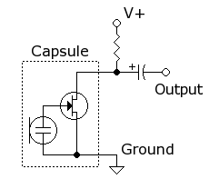
An electret condenser microphone CAPSULE as you are using is actually a condenser microphone ELEMENT, permanently charged by an ELECTRET layer, and with an IMPEDANCE BUFFER circuit INSIDE the little case.  Here is a diagram showing the INTERNAL circuit of the mic capsule, along with a typical output (external) circuit. The resistor "powers" the FET transistor INSIDE the capsule, and the capacitor "taps off" the AC audio signal from the bottom of the resistor.


Suggested reading:  https://en.wikipedia.org/wiki/Electret_microphone


Share me

Digg  Facebook  SlashDot  Delicious  Technorati  Twitter  Google  Yahoo
Smf