Author Topic: TDA1541 DEM oscillator [was: Help identify diode!]  (Read 6012 times)

0 Members and 1 Guest are viewing this topic.

Offline 13hm13Topic starter

  • Frequent Contributor
  • **
  • !
  • Posts: 305
  • Country: de
TDA1541 DEM oscillator [was: Help identify diode!]
« on: June 20, 2018, 04:26:18 pm »
The diode (at position "183" of attached PCB image. It's sitting vertically, between two jumpers, next to jumper 219, parallel to vertical black chassis divider):

It's small, white with a black (cathode) and another green band.

It sits on the -5v rail, near the 7905 reg. One side (cathode) ties to -5v pin of a TDA1541 dac. The other side goes to -5v rails/pins of various servo chips/transistors.

The diode drop about 0.5v .So, I'm assuming it's being used to "further drop/regulate" voltage to the TDA1541A (where the -5 rail measures -4.5).
On the anode side of the diode, all the servo components get all -5.0v.

Problem is, the TDA1541A has a min. -5v rail requirement of -4.5v. And I've seen this value as high as -5.6v on good, working, factory-original CD players.

Again, help me identify the diode (parameters) so I can look for a replacement that has lower Vfd.
« Last Edit: June 24, 2018, 09:02:08 pm by 13hm13 »
 

Online wraper

  • Supporter
  • ****
  • Posts: 16833
  • Country: lv
Re: Help identify diode!
« Reply #1 on: June 20, 2018, 04:33:20 pm »
I don't understand why do you want to replace something that isn't faulty?
 

Offline Gyro

  • Super Contributor
  • ***
  • Posts: 9473
  • Country: gb
Re: Help identify diode!
« Reply #2 on: June 20, 2018, 05:30:16 pm »
Best Regards, Chris
 

Offline 13hm13Topic starter

  • Frequent Contributor
  • **
  • !
  • Posts: 305
  • Country: de
Re: Help identify diode!
« Reply #3 on: June 20, 2018, 08:14:37 pm »
Look in the service manual...

http://freeservicemanuals.info/en/

https://www.hifiengine.com/
Looked at the Serv. Manual before posting the query.
(It's here ...https://www.vintageshifi.com/repertoire-pdf/pdf/telecharge.php?pdf=Marantz-CD-60-Service-Manual.pdf
...for anyone curious)

 It shows "183" as being a jumper, not a diode. Methinks it was some sore of last-minute adjustment Philips made to tweak DAC power current.
« Last Edit: June 20, 2018, 08:20:12 pm by 13hm13 »
 

Offline Gyro

  • Super Contributor
  • ***
  • Posts: 9473
  • Country: gb
Re: Help identify diode!
« Reply #4 on: June 20, 2018, 09:02:08 pm »
So many subtle variants of that original Philips circuit. The CD371/471/472 for example show the TDA1541 driven off the -6V via the 10R safety resistor (3657 on your schematic) with the VDD1 pin voltage marked as -5.25V. Maybe check to see if they reduced the value of the resistor. Also check whether the regulator is a 7905 or a 7906.

So many players, so little difference (apart from opamp choice and front panel features).

If the diode drop is 0.5V then it's too low for a standard one, could well be a schottky, if so, you could change it for a higher current rated one to reduce the Vf.
 
« Last Edit: June 20, 2018, 09:04:47 pm by Gyro »
Best Regards, Chris
 

Offline 13hm13Topic starter

  • Frequent Contributor
  • **
  • !
  • Posts: 305
  • Country: de
Re: Help identify diode!
« Reply #5 on: June 21, 2018, 12:39:36 am »
So many subtle variants of that original Philips circuit. The CD371/471/472 for example show the TDA1541 driven off the -6V via the 10R safety resistor (3657 on your schematic) with the VDD1 pin voltage marked as -5.25V. Maybe check to see if they reduced the value of the resistor. Also check whether the regulator is a 7905 or a 7906.

So many players, so little difference (apart from opamp choice and front panel features).

If the diode drop is 0.5V then it's too low for a standard one, could well be a schottky, if so, you could change it for a higher current rated one to reduce the Vf.
I have several of these vintage Philips CDPs in my "collection".
The unit in question is a Philips CD60 -- supposed to be the same as the Marantz CD60, which is the only SM pdf avail. Also, many of the pdf SMs on the Internet are hack jobs --NOT orig. SMs -- pieced together from whatever was avail.

Anyway, my factory-original Philips CD60 uses a 7905 for BOTH -5v and -6v rails. (Yes, I have seen other Philips that use 7906.)
At the -5v pin (pin 26) of the TDA1541A, there is also a 5-ohm R that drops about 0.4V. I measure -4.31v on pin 26. I did replace the 5R with a 0.5R to squeeze out 0.2V -- which makes it just meet 1541 datasheet's min. requirement for this pin: -4.5v. If I can change that diode for a lower Vf type, I may rest easier ;)

BTW: I have a factory original CD473 that measures -5.65v on pin 26.

So why all the fuss? ... long story ... had a little accident with this CD60. Recovery has been a  long and arduous troubleshooting process. I'm just about home with the repairs. Alas, some hashy noise is audible  when signal (audio) is low-level (quiet passages). I was thinking LSB (least significant bits) handle quiet passages. So maybe the DAC (1541) is not powered correctly. I have swapped it w/another 1541 -- no change.
« Last Edit: June 21, 2018, 12:44:44 am by 13hm13 »
 

Online wraper

  • Supporter
  • ****
  • Posts: 16833
  • Country: lv
Re: Help identify diode!
« Reply #6 on: June 21, 2018, 01:10:15 am »
So why all the fuss? ... long story ... had a little accident with this CD60. Recovery has been a  long and arduous troubleshooting process. I'm just about home with the repairs. Alas, some hashy noise is audible  when signal (audio) is low-level (quiet passages). I was thinking LSB (least significant bits) handle quiet passages. So maybe the DAC (1541) is not powered correctly. I have swapped it w/another 1541 -- no change.
And that's why you want to replace this innocent diode  :palm:. You'd rather should be chasing some dead electrolytic caps. FWIW TDA1541 probably could do is like 12 ENOB of a sunny day. Not that it matters in this case. I even doubt this is DAC circuit related issue at all and could be somewhere further in a way.
 

Offline Gyro

  • Super Contributor
  • ***
  • Posts: 9473
  • Country: gb
Re: Help identify diode!
« Reply #7 on: June 21, 2018, 10:56:43 am »
...  FWIW TDA1541 probably could do is like 12 ENOB of a sunny day. Not that it matters in this case. I even doubt this is DAC circuit related issue at all and could be somewhere further in a way.

Rather an uninformed comment.  :-\

The TDA1541(A) had a guaranteed linearity and monotonicity of 1 LSB max. (16 bit) without external trimming - supply quality permitting of course. It was current output, had no internal digital filter, oversampling or noise shaping and no high frequency MCLK to worry about from the noise perspective. It could also be run static, with simultaneous L/R data, Clk and strobe i/f as well as the normal I2S. It wasn't one of your 24bit sigma deltas with ENOBs of 18bits if you're lucky. It would actually make a good DAC for non-audio use if it wasn't for the ebay ones being mostly fake, old players are the only reliable source.
« Last Edit: June 21, 2018, 11:17:43 am by Gyro »
Best Regards, Chris
 

Offline Gyro

  • Super Contributor
  • ***
  • Posts: 9473
  • Country: gb
Re: Help identify diode!
« Reply #8 on: June 21, 2018, 11:35:17 am »
...
So why all the fuss? ... long story ... had a little accident with this CD60. Recovery has been a  long and arduous troubleshooting process. I'm just about home with the repairs. Alas, some hashy noise is audible  when signal (audio) is low-level (quiet passages). I was thinking LSB (least significant bits) handle quiet passages. So maybe the DAC (1541) is not powered correctly. I have swapped it w/another 1541 -- no change.

Depends what sort of "little accident" it was. If it was an overvoltage event then the SAA7210 or SAA7220 could well be suspect. Check the quality of the 11.2896MHz clock between them too (it must be there though, otherwise the spindle motor would go into runaway). Some judicious heating and cooling might help localize the culprit too.
Best Regards, Chris
 

Offline 13hm13Topic starter

  • Frequent Contributor
  • **
  • !
  • Posts: 305
  • Country: de
Re: Help identify diode!
« Reply #9 on: June 21, 2018, 02:33:27 pm »
The accident: the CD60 tipped off its shelf on one side (left) , and free-fell about 12 inches  to a soft, carpet (which had foam mat underneath).

Some weird issues afterward, including:

The 1541 got very warm. I removed it -- tested it another CDP, it's okay.

Also, laser current adj was off  (CD would not spin up). Not sure how that happened??? Anyway, after adj. of trimmer pot ... it booted and played. Tracks as good as any player.

No PCB or chassis cracks, broken traces. All voltages ok.

Except one nagging issue remains: Some noise (distortion) on music (audio) when recorded level is low (quiet passages, fade-downs, start of fade-ups). When audio level moderate and above, music is clean ( low-level noise is probably still there, but masked by music. It's almost like "dirty dither").

Most of your troubleshooting suggestions are been-there-done-thats: Freeze-sprayed all ICs, etc. No change. Swapped TDA1541A and SAA7220. No change.

It might be the SAA7310 decoder (or something close to it). Or it might be uP chip. Haven't swapped those. But if those LSI multitasking chips were faulty, many other CDP systems (processes) would be affected. Right?

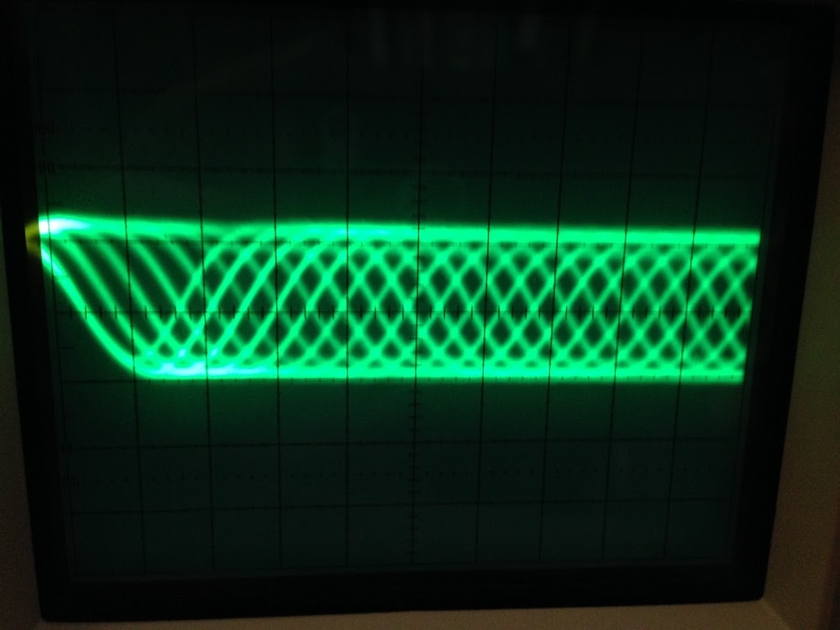
BTW, the eye pattern looks very good:


Offline 13hm13Topic starter

  • Frequent Contributor
  • **
  • !
  • Posts: 305
  • Country: de
Re: Help identify diode!
« Reply #10 on: June 21, 2018, 03:08:22 pm »
...  FWIW TDA1541 probably could do is like 12 ENOB of a sunny day. Not that it matters in this case. I even doubt this is DAC circuit related issue at all and could be somewhere further in a way.

Rather an uninformed comment.  :-\

My reply to wraper:


Offline Gyro

  • Super Contributor
  • ***
  • Posts: 9473
  • Country: gb
Re: Help identify diode!
« Reply #11 on: June 21, 2018, 04:47:17 pm »
For mechanical shock, one other possibility would be a cracked SMD capacitor (as the board is phenolic), the DEM oscillator capacitor (depending on whether it's an A or non-A) between pins 16 an 17 for example. Loss of DEM would probably cause low level noise. Curious about the laser current, it implies that something 'shifted' possibly in the optical assembly, causing degraded laser output or feedback, the pot itself would be a bit unlikely.

(P.S. Be careful on winding wraper up)

EDIT: Just one more thought - along the lines of possible damage to the optical assembly. Servos working overtime could pollute the supply rails and cause low level noise. You should be able to check this if you have a scope.
« Last Edit: June 21, 2018, 05:36:24 pm by Gyro »
Best Regards, Chris
 

Offline 13hm13Topic starter

  • Frequent Contributor
  • **
  • !
  • Posts: 305
  • Country: de
Re: Help identify diode!
« Reply #12 on: June 21, 2018, 05:44:59 pm »
For mechanical shock, one other possibility would be a cracked SMD capacitor (as the board is phenolic), the DEM oscillator capacitor (depending on whether it's an A or non-A) between pins 16 an 17 for example. Loss of DEM would probably cause low level noise. Curious about the laser current, it implies that something 'shifted' possibly in the optical assembly, causing degraded laser output or feedback, the pot itself would be a bit unlikely.

(P.S. Be careful on winding wraper up)
BINGO!!!!!!!
You nailed it with DEM!

It was not cracked, because there was no cap. I replaced it with a custom-built  DEM ckt on veroboard (same as a veroboard clock ckt -- see attached photo). I build a lot of experimental modules like that, based on threads on the DIY audio forums.
Anyway, it was all loosey goosey -- suspended just by its own wires; I was planing on permanently attaching after I finished experimentation. And it went for a ride during the fall. I'll have to troubleshoot the DEM ckt now.

Nice call!!

In the photo, the DEM veroboard module is in the upper left. A clock and /2 ckt vero is on the bottom. Not shown (cropped) was another vero I/V module (this was an opamp DIP plug-n job and got knocked out when the CD60 fell).
 

Offline Gyro

  • Super Contributor
  • ***
  • Posts: 9473
  • Country: gb
Re: Help identify diode!
« Reply #13 on: June 21, 2018, 05:52:26 pm »
Quote
Nice call!!

Thanks. One tries. ;)

I played around with DEM reclocking myself but have yet to come up with a definitive conclusion - I know how it sounds when it's not working though!


Best Regards, Chris
 

Offline 13hm13Topic starter

  • Frequent Contributor
  • **
  • !
  • Posts: 305
  • Country: de
Re: Help identify diode!
« Reply #14 on: June 21, 2018, 07:30:43 pm »
Quote
Nice call!!

I played around with DEM reclocking myself but have yet to come up with a definitive conclusion -
Ditto.
There's long thread on diyaudio.com on DEM reclocking the TDA1541. I tried Henk's original but found it only different than stock cap. Another guy (tubee)  posted a hand-drawn (Dave-CAD style) iteration -- and that was a noticeable improvement. See photos.
Both Henk and tubee are from NL -- original Philips engineers, I think.

BTW: Years ago, when I experimented with DEM (cap or ckt), I found that on some TDA1541A's, you could run it w/o cap (no distortion); on other 1541s, it'd distort like crazy. Some info here: http://www.diyaudio.com/forums/digital-line-level/11949-tda1541-dem-reclocking-post1871274.html
« Last Edit: June 21, 2018, 07:47:14 pm by 13hm13 »
 

Offline 13hm13Topic starter

  • Frequent Contributor
  • **
  • !
  • Posts: 305
  • Country: de
Re: Help identify diode!
« Reply #15 on: June 24, 2018, 04:00:42 pm »
I played around with DEM reclocking myself but have yet to come up with a definitive conclusion - I know how it sounds when it's not working though!
A follow-up regarding the DEM reclocker...
After the accident, it seems I can get no DEM reclockers to work. The one that went thru the accident checked out fine; but with it in the ckt, it created that low-level noise noted earlier. So I put in the stock cap, and noise issue was history.
I have another exactly identical (Henk) DEM clock to the one that was in the accident -- this one also causes low-level noise.
And, finally, I have yet another species of DEM reclocker (tubee) that I know worked before in the same CD60. This one also causes low-level noise.
Note: The low-level noise is exactly (audibly) identical to how a TDA1541 behaves with pin 16/pin 17 open (i.e., no cap; no DEM ckt; nothing!)
Only the cap restores original sound (i.e., full-fidelity, sans noise).
Before accident, the CD60 behaved well with various species of DEM re-clockers installed.
This is a weird mystery, like the laser power being out-of-adjustment after accident.
All else with the CD60 -- performance, operation --  seems normal. But it would be nice to resolve the DEM mystery. I originally kept it in this CD60 as it was a marked sonic  improvement over the stock cap.
« Last Edit: June 24, 2018, 04:02:21 pm by 13hm13 »
 

Offline Gyro

  • Super Contributor
  • ***
  • Posts: 9473
  • Country: gb
Re: Help identify diode!
« Reply #16 on: June 24, 2018, 06:33:01 pm »
I guess it's possible that there was some damage to the DEM oscillator. It's an emitter coupled multivibrator, biassed by current sources (all of the logic is ECL). Possibly the biassing may have been damaged by an accidental short to one of the supply rails, but not enough to stop the basic oscillator working with the pins just capacitively coupled. I think the TDA1541 was capable of running on an on-chip capacitor, whereas the TDA1541A moved to an external capacitor for greater stability. Philips included the capacitor footprint on all the PCBs for compatibilty, the same way as they did with the connection of the removed the 'System clock' function on Pin 4 between the two versions.

With just the cap, you should be able to scope the DEM pins (use AC coupling) to check for the characteristic multivibrator waveform - hopefully still symmetrical, pictures in the DIY Audio thread irrc. I know from the thread, and personal experience that it is quite tricky to get reliable external override of the DEM clock. From my results it does make a difference, but over the years I've struggled to  decide whether difference is 'better' or just 'different', the problem with all subjective things.

I'm not sure if you have them but I've attached the IEEE Journal Philips technical papers relating to the design of the TDA1540 (14 bit) and the TDA1541 (16 bit). The reason for including the 14 bit one is that the complete internal circuit diagram (Fig. 7) actually shows the internals of the DEM oscillator (near the bottom left corner).

I hope this helps. BTW it may be worth editing the thread title to something a bit more descriptive, as I think you're past diodes. Something like TDA1541 DEM oscillator issue, that hopefully won't attract the attention of the 'audiophool' hunter crowd.
« Last Edit: June 24, 2018, 06:35:50 pm by Gyro »
Best Regards, Chris
 
The following users thanked this post: 13hm13

Offline 13hm13Topic starter

  • Frequent Contributor
  • **
  • !
  • Posts: 305
  • Country: de
DEM oscillator, TDA1541
« Reply #17 on: June 25, 2018, 03:18:29 pm »
I guess it's possible that there was some damage to the DEM oscillator.
The one inside the TDA1541A?
Not sure I noted it earlier, but post-accident, I did swap out the TDA1541A with another one. No change: same low-level noise issue with outboard DEM; and no noise with cap.

As far as the outboard "project" DEM modules ... as I said in my last post, three separate modules produce noise.

BTW, a minor correction:
The DEM module in the accident was Henk, not tubee. So the module show in images (earlier post) is Henk, not tubee. And they are different: e.g., tube only relies on +5v rail to power logic ICs, etc.


With just the cap, you should be able to scope the DEM pins (use AC coupling) to check for the characteristic multivibrator waveform - hopefully still symmetrical, pictures in the DIY Audio thread irrc.
Been there, done that a week ago ;) With just the cap, I 'scoped it:  waveform does look exactly like DIYaudio posts by ecdesigns:
(top image is cap; bottom is outboard DEM)


Quote
I know from the thread, and personal experience that it is quite tricky to get reliable external override of the DEM clock. From my results it does make a difference, but over the years I've struggled to  decide whether difference is 'better' or just 'different', the problem with all subjective things.
Ditto experience, but the tubee DEM was good 'nough to be a keeper! I only wish I could get the outboards to cooperate again ;)
Quote

I'm not sure if you have them but I've attached the IEEE Journal Philips technical papers relating to the design of the TDA1540 (14 bit) and the TDA1541 (16 bit). The reason for including the 14 bit one is that the complete internal circuit diagram (Fig. 7) actually shows the internals of the DEM oscillator (near the bottom left corner).
Thx for the papers.
Over on PFM, Martin Clark posted some captures from a Philips paper on DEM. The paper suggests an outboard DEM topology.
If you have the full paper, I wouldn't mind seeing it.


Offline Gyro

  • Super Contributor
  • ***
  • Posts: 9473
  • Country: gb
Re: TDA1541 DEM oscillator [was: Help identify diode!]
« Reply #18 on: June 25, 2018, 06:18:33 pm »
Oops, sorry, I forgot you had tried another 1541a, that excludes the internal oscillator, obviously.

Thanks for the paper extracts, no I hadn't seen those before. Sadly, I don't have that paper, I really wish I did, judging from those snapshots! If you do ever happen to find a full copy...

The only other Philips paper I have is the original DEM description, based on a [Edit: 12 bit] test chip, so presumably pre-dating the other two. Attached for your reference.


P.S. That override circuit is one I've seen implemented on some Grundig players, I always wondered where it came from.
« Last Edit: June 25, 2018, 07:12:21 pm by Gyro »
Best Regards, Chris
 

Offline 13hm13Topic starter

  • Frequent Contributor
  • **
  • !
  • Posts: 305
  • Country: de
Re: TDA1541 DEM oscillator [was: Help identify diode!]
« Reply #19 on: August 04, 2021, 06:35:27 pm »
Because I posted on this topic here on EEVBlog, instead of continuing the troubleshooting where it initially began (DIYAudio.com), I was banned (Jan. 2020) from DIYAudio.com after a 13-year membership there.
The issue was literally solved in HOURS here on EEVBlog, instead of many days/weeks over on DIYA.

The fact that none of their expert ("audio") members could solve the issue EMBARRASSED the crap out of them. And I let 'em know it ;)

https://www.diyaudio.com/forums/digital-source/323711-philips-marantz-cd-60-spinning-post5469484.html

https://www.diyaudio.com/forums/digital-source/323711-philips-marantz-cd-60-spinning-post5469588.html

https://www.diyaudio.com/forums/digital-source/323711-philips-marantz-cd-60-spinning-post5935592.html


Share me

Digg  Facebook  SlashDot  Delicious  Technorati  Twitter  Google  Yahoo
Smf