Author Topic: How does it oscillate?  (Read 6647 times)

0 Members and 1 Guest are viewing this topic.

Offline fast_eddyTopic starter

  • Newbie
  • Posts: 6
How does it oscillate?
« on: October 28, 2012, 10:52:42 pm »
I’ve got this circuit from Colin Mitchell’s Talking Electronics web site and read the explanation of how it works.
I understand how Q1 gets switched on as C2(10u) gets charged hence turning on Q2 and LED.  But I don’t understand how the circuit turns off.
Could someone explain please how the circuit oscillate? What is the purpose of C1 (10n)?


Offline IanB

  • Super Contributor
  • ***
  • Posts: 11891
  • Country: us
Re: How does it oscillate?
« Reply #1 on: October 28, 2012, 11:07:33 pm »
I don't know the circuit, but I would guess that when Q1 turns on it starts to conduct through its base-emitter junction and starts to discharge C2. When Q1 turns on it also turns on Q2 and the forward current through D1 passing through R2 lifts the top of R2 and the +ve side of C2 above ground, thus helping to "tip the charge out" of C2 (like lifting a bucket above ground to empty it).

When C2 is discharged Q1 will start to turn off, which will cause Q2 to start to turn off. This will cause the voltage atop R2 to start falling, which will turn off Q1 even faster. There will be a chain reaction causing Q1 to be turned hard off, and now C2 will start charging through R3 all over, and the cycle starts again.
 

Offline PA4TIM

  • Super Contributor
  • ***
  • Posts: 1161
  • Country: nl
  • instruments are like rabbits, they multiply fast
    • PA4TIMs shelter for orphan measurement stuff
Re: How does it oscillate?
« Reply #2 on: October 28, 2012, 11:55:37 pm »
Q1 goes on, base is positive, so it pulls the base of Q2 negative, Q2 conducts. C2 now sees a more positive charge on the anode then the cathode and gets charged. When fully charged the kathode is negative and pulls the base of Q1 down. After this the base of Q2 gets more positive and cuts off.
After this the whole things starts over again.
www.pa4tim.nl my collection measurement gear and experiments Also lots of info about network analyse
www.schneiderelectronicsrepair.nl  repair of test and calibration equipment
https://www.youtube.com/user/pa4tim my youtube channel
 

Offline fast_eddyTopic starter

  • Newbie
  • Posts: 6
Re: How does it oscillate?
« Reply #3 on: October 29, 2012, 01:50:06 am »
What is the purpose of C2 (10n)?
 

Offline BravoV

  • Super Contributor
  • ***
  • Posts: 7547
  • Country: 00
  • +++ ATH1
Re: How does it oscillate?
« Reply #4 on: October 29, 2012, 12:46:33 pm »
Noticed that the schematic was made in ltspice, why not simulate it yourself with and without that C2 and learn from there.

Although I can't explain it, I learned a lot of analog stuff that way.  ;)

Online Psi

  • Super Contributor
  • ***
  • Posts: 9951
  • Country: nz
Re: How does it oscillate?
« Reply #5 on: October 29, 2012, 01:07:20 pm »
I built it and had a play in LTspice this morning.  Sorry, i didn't save it.

It seemed quite critical of the LED specs and would produce a very short pulse of 50mA with an initial spike up to a few hundred.
Greek letter 'Psi' (not Pounds per Square Inch)
 

Offline PA4TIM

  • Super Contributor
  • ***
  • Posts: 1161
  • Country: nl
  • instruments are like rabbits, they multiply fast
    • PA4TIMs shelter for orphan measurement stuff
Re: How does it oscillate?
« Reply #6 on: October 29, 2012, 01:53:00 pm »
I do not know the function, it could be to be sure it stays at low frequency flip-flopping instead of real AC oscillating,

Why not plug it in a breadboard, that is done quicker as spice or typing the question  ;) just let it out, take a smaller, bigger and measure or look what the difference is.
www.pa4tim.nl my collection measurement gear and experiments Also lots of info about network analyse
www.schneiderelectronicsrepair.nl  repair of test and calibration equipment
https://www.youtube.com/user/pa4tim my youtube channel
 

Offline NewBeginner

  • Regular Contributor
  • *
  • Posts: 74
  • Country: 00
Re: How does it oscillate?
« Reply #7 on: October 29, 2012, 05:54:33 pm »
I may be saying something stupid (please correct me if I am wrong) but I think that the role of C1 is to prevent the circuit from latching.
As Psi stated it seems that the working of the circuit depends on the specs of the LED used (at least according to the simulation).
By playing with the values of C1 and R1 I was able to get it to oscillate with more LEDs (in LTSpice).

So, is the role of C1 to prevent latching so that oscillation can continue?

Thank you :)
« Last Edit: October 30, 2012, 08:08:12 am by NewBeginner »
 

Offline fast_eddyTopic starter

  • Newbie
  • Posts: 6
Re: How does it oscillate?
« Reply #8 on: October 29, 2012, 09:42:22 pm »
Thank you to those who replied.

I have tried to simulate the circuit using LTSpice but couldn't get it to oscillate!. It just shows a steady state except the first few micro seconds.
I built the circuit on a breadboard and probed it with DSO, printed out waveforms and studied it over a few months but with my limited knowledge of electronics (diploma from a NSW TAFE ) I am unable to explain exactly how the LED turns on and off.

I have a basic understanding of AC and DC principles, transistors and RC circuits.  I can see the effect of C2 (with or without it or with a different values) but I don't understand how it works or if it is needed there at all.
 

Offline fast_eddyTopic starter

  • Newbie
  • Posts: 6
Re: How does it oscillate?
« Reply #9 on: October 29, 2012, 09:54:38 pm »
I'm sorry about the Typo -  What I meant to ask was the function of  C1 (10nF Cap)  NOT C2(10uF).
 

Offline NewBeginner

  • Regular Contributor
  • *
  • Posts: 74
  • Country: 00
Re: How does it oscillate?
« Reply #10 on: October 30, 2012, 08:12:11 am »
In my previous reply I was referring to C1 (and R1 - sorry for the mistake) :).  I have updated the reply.
Anyway, I m also a beginner in electronics, so maybe somebody with more knowledge can shed a light on the purpose of C1.
I am also curious if I got it right :)

Thank you :)
 

Offline Chryseus

  • Regular Contributor
  • *
  • Posts: 87
  • Country: gb
    • My Website
Re: How does it oscillate?
« Reply #11 on: October 30, 2012, 11:30:17 pm »
From looking at it I think it works as follows:

On power on Q1 and Q2 are off.
C2 charges through R3 and R2 (R2 can largely be ignored due to low value) causing the voltage on the base of Q1 to rise.
At ~0.7V Q1 turns on providing a path to ground through the base-emitter junction of Q2, C1 bypasses R1 allowing for a brief high current pulse, LED limited by R2.
C2 shortly after this has discharged enough through the base-emitter junction of Q1 for it to turn off, the charge stored on C1 discharges through R1.
Repeat.

End result is brief high current pulses through the LED, which you really want or it would be hard to see.
From the values I estimate the off time to be around 800ms (probably less as some charge will remain on C1 depending on how long it takes Q1 to turn off) and an on time in the region of 20us, the actual value of C1 is of little consequence as long as it's not high enough to remain charged between cycles..
 

Offline PA4TIM

  • Super Contributor
  • ***
  • Posts: 1161
  • Country: nl
  • instruments are like rabbits, they multiply fast
    • PA4TIMs shelter for orphan measurement stuff
Re: How does it oscillate?
« Reply #12 on: October 30, 2012, 11:45:27 pm »
No, i do not think so. The base of Q1 is through the 330K at Vcc. The current will flow imediatly through the base and the transistor conductes and pulls the base to 0,6V. And so the capacitor. The RC time is much longer as the time the transistor needs to go in conduction through the 330K

In your case C2 is polarised the wrong way and the paracitic diode in the oxide will leak the current if voltage is around 1V, maybe 2V for a HV type.

If Q1 pulls down and Q2 starts to conduct then C2 will be charged. Because the anode becomes possitive the cathode becomes negative and this negative current closes Q1 and then all starts over again.
« Last Edit: October 30, 2012, 11:56:22 pm by PA4TIM »
www.pa4tim.nl my collection measurement gear and experiments Also lots of info about network analyse
www.schneiderelectronicsrepair.nl  repair of test and calibration equipment
https://www.youtube.com/user/pa4tim my youtube channel
 

Offline fast_eddyTopic starter

  • Newbie
  • Posts: 6
Re: How does it oscillate?
« Reply #13 on: October 30, 2012, 11:56:59 pm »
Chryseus, how does C2 gets discharged through R1?  Does current from C2 flows up through the collector and then through the base of PNP transistor???
I understand how NPN and PNP transistor get turned on but I still don't quite follow how NPN (and hence PNP) transistor starts to turn off .
 

Offline Chryseus

  • Regular Contributor
  • *
  • Posts: 87
  • Country: gb
    • My Website
Re: How does it oscillate?
« Reply #14 on: October 31, 2012, 02:11:25 am »
No, i do not think so. The base of Q1 is through the 330K at Vcc. The current will flow imediatly through the base and the transistor conductes and pulls the base to 0,6V. And so the capacitor. The RC time is much longer as the time the transistor needs to go in conduction through the 330K

In your case C2 is polarised the wrong way and the paracitic diode in the oxide will leak the current if voltage is around 1V, maybe 2V for a HV type.

If Q1 pulls down and Q2 starts to conduct then C2 will be charged. Because the anode becomes possitive the cathode becomes negative and this negative current closes Q1 and then all starts over again.

Just to make sure I'm not talking out my arse I put it in a simulator, as I thought the base voltage of Q1 does ramp up to ~0.7V when switched on, remember in the initial state the capacitor looks like a dead short so you have 330k in series with 22 ohm, that means the voltage applied to the base will be around 300uV not enough to turn it on, as it charges up it should perform as explained in my previous post, it's easy to overlook the importance of R2.

C2 discharges directly through R1, a charged capacitor acts rather like a small battery independent of the circuit ground, same as putting a battery in parallel with a resistor.
 

Offline PA4TIM

  • Super Contributor
  • ***
  • Posts: 1161
  • Country: nl
  • instruments are like rabbits, they multiply fast
    • PA4TIMs shelter for orphan measurement stuff
Re: How does it oscillate?
« Reply #15 on: October 31, 2012, 08:36:55 am »
In a perfect spice world there is no dielctric absorbtion ( in case the cap was used the other way around) and caps behave like dead shorts if reversed biased. If you never have tried it ( not spice) then please try, you will see the Vf will be between 1 and 2V and with a current meter in serie you will see the current flow will be allmost unlimmited. Heating up the cap and the result is the famous big bang so wear protection.
So in real life a reversed used electrolytic cap will behave as a diode with a Vf of minimum 1V. So there is a conducting Vf=1V diode parallel with the base-emitter diode at 0.6-0.7V of Q1. So current will flow through the base of Q1

So Q1 starts to conduct straight away ( with a real electrolytic cap)
Turning Q2 on. Q2 will be running 2.3 mA through it's base , neglecting the cap there will be - minimum 135 mA through the led and R 22 Ohm, so the led flashes ( if you are lucky it survives) The Voltdrop over the 22Ohm wil be 3V. The positive side of the cap will see 3V , the negative is at 0.6V so the cap charges to 3V very quick, not limmited by anything, so the current will be very short much higher as 135 mA ( that is probably why the led survives) and as soon as the cap is charged (probably  a few us) the base of Q1 will drop under 0.6V turning that Q1 and in turn Q2 off. The cap discharges very quick ( less as 1ms or so) through the 22 Ohm until it is at zero volt and turning the cap in a forward biased diode again and swiching on Q1 by lifting the base to about 1V and all starts over
www.pa4tim.nl my collection measurement gear and experiments Also lots of info about network analyse
www.schneiderelectronicsrepair.nl  repair of test and calibration equipment
https://www.youtube.com/user/pa4tim my youtube channel
 

Offline Chryseus

  • Regular Contributor
  • *
  • Posts: 87
  • Country: gb
    • My Website
Re: How does it oscillate?
« Reply #16 on: October 31, 2012, 02:30:06 pm »
Very interesting I would have never thought of using a capacitor in such a manner.
Another case of when not to trust spice I guess.  :P
 

Offline fast_eddyTopic starter

  • Newbie
  • Posts: 6
Re: How does it oscillate?
« Reply #17 on: November 01, 2012, 12:25:44 am »
I think I understand what PA4TIM is trying to say about 10uF cap but when I capture the waveform on my DSO the voltage on the -ve side of 10uF cap starts to increase from 0V to about 0.6V before NPN transistor starts to conduct.  The voltage on the -ve lead of 10uF cap does not show 1V (or there about) when I switch the circuit on and do a single shot capture. I attach the DSO waveform.

Anyway, as far as my original question; how does the circuit turn off?, I think if I understand correctly, the -ve lead of C2 (10uF cap) and the base of NPN becomes -ve wrt ground and turns the NPN transistor off.  Is that what happens?  But what about current coming from 330k resistor? Doesn't that keep the NPN transistor on???
 

Offline tlu

  • Regular Contributor
  • *
  • Posts: 145
Re: How does it oscillate?
« Reply #18 on: November 01, 2012, 05:29:01 am »
As I'm also a newbie to electronics, I'm very curious how it would oscillate as well. When the electrolytic cap (C2) is fully charged, I can see how that would turn on the Q1 giving it a forward bias of 0.6V. How does it discharge? Is it back through R3 and to the battery? During this discharge phase, is there enough current to briefly light the LED?

What I do not understand is how does C2 gets discharged when you have a constant supply voltage from the battery? I know that when the supply voltage fully charge C2 it will sit there with this charge unless a load (in this case the LED) pulls from it. So, if the LED is not in the circuit, will the oscillations still happen?


Offline PA4TIM

  • Super Contributor
  • ***
  • Posts: 1161
  • Country: nl
  • instruments are like rabbits, they multiply fast
    • PA4TIMs shelter for orphan measurement stuff
Re: How does it oscillate?
« Reply #19 on: November 01, 2012, 08:49:57 am »
Nice, that is the Spirit, no spice but real measurements, i learn something too. I have done many experiments with caps but i have tested for the diode phenomen ( desrcibed in many books about caps) only using a current and voltage meter ( with my reformer). The current was limmited to 15 mA, the Vf voltages was  1 to 2 V depending the cap straight away. But here I see the cap still behaves like a cap under that Vf. It is not good for an electrolityc cap to be reversed biased, the oxide layer dammages. But it stayes under the Vf here. My RC time was much smaller and without the scope hooked to it, it just looked like the diode behaviour was there straight away. ( we are talking ms and my eye is not that fast)

In your case you misunderstood me on one point, you will not see the 1V that I meant because the base will not allow this. If you hook up only a cap reversed and a resistor you will see the cap ramping up to the Vf and not higher. If you turn it around it will ramp up to the V+ of the powersupply.

But for the rest you see my description. As soon as Q1 conducts you see the plus side of the cap getting loaded very fast. This ís the current through Q2 who starts to conduct as soon as Q1 conducts.
You see that under influence of the strong electric field the other side of the cap becomes negative and this is cutting off Q1 and in turn Q2 ( and I think the other cap makes the short delay between the two ( where the cap is loaded) i would think the cp would become laded to more as 1V. Then current is higher as I thought or your led had a higher Vf ( i took 2V like most red leds are)
The discharge of the 10 uF is as follow. The cap charged by Q2 is positive so there is a shortage on electrons at that side, that attracts electrons to the other side through the basis of Q1.
As soon as Q1 cutts off the electron low stops. Q2 cuts off too and the electrons flow through the 22 ohm to the positive site and discharging it to zero.

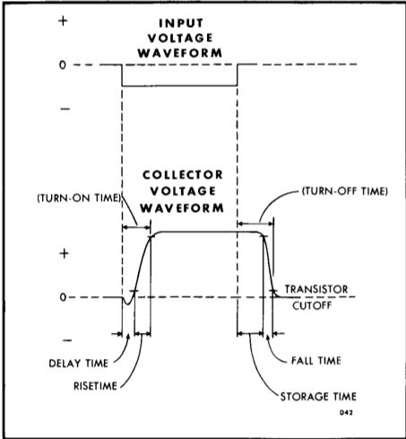
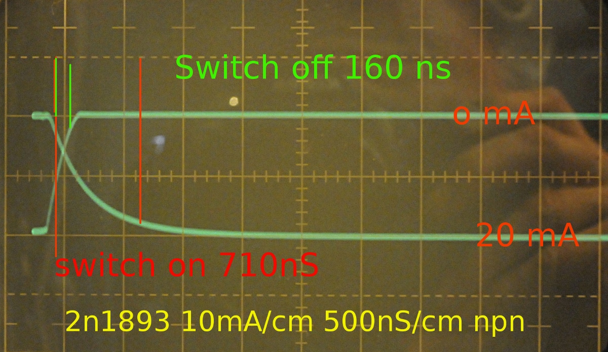
A transistor also needs some time for that. ( a transistor has a rise and fall time) but that's very short. This is also a sort of ramping because the capacitances it has ( we are talking pF here, but many nF for MOSFET gates. Not a problem here just some extra info. I have a Tek plugin ( type R plugin) that measures that on a scope and it is nice to see that happening.


« Last Edit: November 01, 2012, 10:26:45 am by PA4TIM »
www.pa4tim.nl my collection measurement gear and experiments Also lots of info about network analyse
www.schneiderelectronicsrepair.nl  repair of test and calibration equipment
https://www.youtube.com/user/pa4tim my youtube channel


Share me

Digg  Facebook  SlashDot  Delicious  Technorati  Twitter  Google  Yahoo
Smf