The OP has a meter with +/- direction with a letter 'g' printed on the face-plate. He want's to use it as a sensitive current meter for extremely low currents. He can easily use an op-amp circuit to do so.
Brian, I'm sorry to say, well intentioned as you are, that you are very much on the wrong track.
Here is an example circuit:
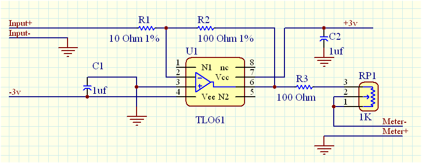
Note to change R2 to 1K, or 10K, or 100K to increase the sensitivity/gain of the circuit.
The input impedance is 10 ohm within the range of the circuit.
There are better op-amps than TLO61, just use a fet input and low voltage offset opamp.
I chose +/-3v as the power supply, basically 3 lithium coin cells, but, you can use 2 9v batteries to get +/-9v.
For below Picoamp and Fentoamp, this circuit will not suffice.
Actually going for higher voltage supply, you will need to change the r3 to 1k and the trimpot to 10k.
Yes, he wants to measure lower currents than the meter natively does (+/-500uA) but you are offering a solution with a 10 ohm input impedance. He needs to
increase the input impedance,
not reduce it. Furthermore, you've just given him a design for a voltage input circuit, not a current input circuit.
Here's a very simple design for a current input amplifier that amplifies by 10 (for the current meter's 120 ohm coil resistance). It's produced in LTSpice, the forum's favourite circuit simulator, and the LTSpice .asc file is also attached.

Rsense is simply set in ratio to the meter winding resistance, in the amplification ratio you want. In this case the amplification ratio is 10, the meter winding is 120

so Rsense is simply 1200
. This results in a complete system with a full scale swing of +/-50 uA. If you want a current gain of 100 then Rsense becomes 12k and so on.
The op amp is only being asked to operate at unity gain, whatever the current gain you call for; so it will have a non-critical gain bandwidth. Op amp input impedance (i.e. input bias current) does matter, so it is necessary to pick a JFET/CMOS input amplifier but a cheap one will do. A TL071 or similar would fit the job in hand fine.
This is just a sketch, not a complete schematic and obvious consideration needs to be given to power supplies, input protection and overall stability. This is probably perfectly stable into the meter impedance given but you never really can tell until you try it with real electrons.
As the maximum input voltage is set by the full scale voltage of the meter (+/-500uA * 120
) = +/- 60 mV, input protection is easy, a pair of parallel diodes to limit the input voltage across Rsense to 1 diode drop will do the job admirably. Diode reverse leakage currents may be an issue, if so, substituting a pair of diode wired small signal bipolar transistors for the diodes will keep leakage to the level of a few picoamps.


