Author Topic: How would you make such circuit?  (Read 4844 times)

0 Members and 1 Guest are viewing this topic.

Offline ZeTeXTopic starter

  • Frequent Contributor
  • **
  • !
  • Posts: 610
  • Country: il
  • When in doubt, add more flux.
How would you make such circuit?
« on: October 14, 2016, 04:58:04 pm »
Lets say I have 5 leds, lets call them A B C D E.
I have a voltage source that can vary it out from 2-10V for example, now I need a circuit that when the voltage source output 3V (for example), led "A" turns on. now when the voltage source output 4V, led "B" turns on but led "A" turns off., then when the voltage source output 5V, led "C" turns on but led B turns off, so only 1 led at the time turns on, so I cant just put a few comparators with the non inverting input sensing the voltage and the inverting input having the threshold voltage because then A and B for example are going to turn on.
0 = off, 1 = on

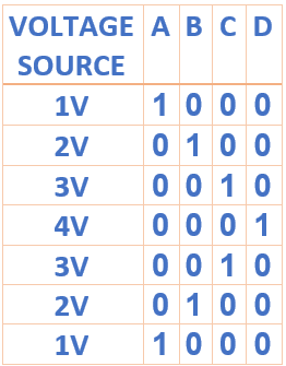
*under no circumstances I can have 2 LEDs turn on at the same time (for more then a few ms), there has to be ALWAYS at least 1 led on, the circuit has to be that there is no way of 2 LEDs turning on at the same time.
« Last Edit: October 14, 2016, 05:14:06 pm by ZeTeX »
 

Offline elgonzo

  • Supporter
  • ****
  • Posts: 688
  • Country: 00
Re: How would you make such circuit?
« Reply #1 on: October 14, 2016, 05:11:14 pm »
What if the output is 3.5V?
You could use a LM3914, no?
« Last Edit: October 14, 2016, 05:14:47 pm by elgonzo »
 

Offline chris_leyson

  • Super Contributor
  • ***
  • Posts: 1541
  • Country: wales
Re: How would you make such circuit?
« Reply #2 on: October 14, 2016, 05:11:37 pm »
 

Offline Lee Leduc

  • Regular Contributor
  • *
  • Posts: 84
  • Country: us
 

Offline ZeTeXTopic starter

  • Frequent Contributor
  • **
  • !
  • Posts: 610
  • Country: il
  • When in doubt, add more flux.
Re: How would you make such circuit?
« Reply #4 on: October 14, 2016, 05:15:35 pm »
What if the output is 3.5V?
then the "C" led is going to stay on till the voltage hit 4V and then "D" is going to turn on.
LM3914 is a dot mode is a problem, I taught about using it but there is a problem that 2LEDs can be on at the same time, I can not have this.
« Last Edit: October 14, 2016, 05:18:56 pm by ZeTeX »
 

Offline elgonzo

  • Supporter
  • ****
  • Posts: 688
  • Country: 00
Re: How would you make such circuit?
« Reply #5 on: October 14, 2016, 05:21:43 pm »
What if the output is 3.5V?
then the "C" led is going to say on till the voltage hit 4V and then "D" is going to turn on.
LM3914 is a dot mode is a problem, I taught about using it but there is a problem that 2LEDs can be on at the same time, I can not have this.
You could still go ahead with comparators. Process the output of the comparators through a few logic gates and/or some demuxer ICs (such as the 74HC(T)154 or 74HC4067, for example) to select the appropriate LED for whatever combination of comparator output values.
« Last Edit: October 14, 2016, 05:58:34 pm by elgonzo »
 

Offline oldway

  • Super Contributor
  • ***
  • !
  • Posts: 2172
Re: How would you make such circuit?
« Reply #6 on: October 14, 2016, 06:33:46 pm »
This is a good exercice for a beginner.....Do the circuit yourself.
Some ideas: Use a LM324 (four comparators) and a logic with diodes and transistors so the comparator of the highest voltage inhib the output of the comparators of lower voltages.
Enjoy !
 

Offline kripton2035

  • Super Contributor
  • ***
  • Posts: 2581
  • Country: fr
    • kripton2035 schematics repository
Re: How would you make such circuit?
« Reply #7 on: October 14, 2016, 07:25:50 pm »
use some pic, atmel, cypress microcontroller with 1 analog input and 4 digital outputs
program the chip the way you want.
 

Offline Ian.M

  • Super Contributor
  • ***
  • Posts: 12852
Re: How would you make such circuit?
« Reply #8 on: October 14, 2016, 07:56:10 pm »
Actually, this is absolutely trivial.  No logic required, only OPAMPs.
 

Online mariush

  • Super Contributor
  • ***
  • Posts: 5016
  • Country: ro
  • .
Re: How would you make such circuit?
« Reply #9 on: October 14, 2016, 08:33:49 pm »
Well, a cheap microcontroller with internal voltage reference and an adc would be enough if you can power it separately with at least 1.8v or something that's above the forward voltage of each led (at least around 1.7v for red leds)
Even a 6 pin micro (I think PIC10F320 would work just fine, but PIC12LF1571 is really cool and even easier to use) would be enough as you can control 4 leds with just 2 i/o pins and you're left with  voltage and ground pins and two pins, one for adc and one extra.

If you don't want to depend on separate power, there are microcontrollers which work from around 0.9v up to 3.3v or 3.6v, a simple zener diode would block the input voltage from going above maximum voltage , a couple of resistors could be a voltage divider to keep the voltage less than the reference voltage you configure in the microcontroller (could be 1.024v or something like that) but when the input voltage is 1v or higher (less than 2v) you'd have to also add a voltage doubler or something like that on the pin from where the 1v is turning on.

LM3914 is expensive, a microcontroller can be less than 0.5$
 

Offline ZeTeXTopic starter

  • Frequent Contributor
  • **
  • !
  • Posts: 610
  • Country: il
  • When in doubt, add more flux.
Re: How would you make such circuit?
« Reply #10 on: October 14, 2016, 08:56:04 pm »
Well, a cheap microcontroller with internal voltage reference and an adc would be enough if you can power it separately with at least 1.8v or something that's above the forward voltage of each led (at least around 1.7v for red leds)
Even a 6 pin micro (I think PIC10F320 would work just fine, but PIC12LF1571 is really cool and even easier to use) would be enough as you can control 4 leds with just 2 i/o pins and you're left with  voltage and ground pins and two pins, one for adc and one extra.

If you don't want to depend on separate power, there are microcontrollers which work from around 0.9v up to 3.3v or 3.6v, a simple zener diode would block the input voltage from going above maximum voltage , a couple of resistors could be a voltage divider to keep the voltage less than the reference voltage you configure in the microcontroller (could be 1.024v or something like that) but when the input voltage is 1v or higher (less than 2v) you'd have to also add a voltage doubler or something like that on the pin from where the 1v is turning on.

LM3914 is expensive, a microcontroller can be less than 0.5$
But I don't know how to code :(
Ian.M gave a good solution to the problem, and is even cheaper then a micro-controller.
 

Online mariush

  • Super Contributor
  • ***
  • Posts: 5016
  • Country: ro
  • .
Re: How would you make such circuit?
« Reply #11 on: October 14, 2016, 09:30:21 pm »

But I don't know how to code :(
Ian.M gave a good solution to the problem, and is even cheaper then a micro-controller.
Cheaper is relative. The opamp itself may be cheaper, but you have bigger chip (more pins), you have extra resistors and it requires a higher voltage to work (i see 9v on schematic). Sometimes the pcb space is worth something.
But I agree, for just one project it's not worth it. If you plan on doing more projects in the future it's worth buying a programmer and as for learning, you can find a huge amount of tutorials and example code online to teach you how to initialize a microcontroller and start/stop leds or read a voltage from one pin.
« Last Edit: October 14, 2016, 09:33:06 pm by mariush »
 

Offline Ian.M

  • Super Contributor
  • ***
  • Posts: 12852
Re: How would you make such circuit?
« Reply #12 on: October 14, 2016, 10:11:20 pm »
Use a true rail to rail quad opamp, and you can run it from 5V.  However you'll then need to use an input divider to cope with the input range going above the supply rail and add a resistor above the reference chain to rescale it accordingly.   

The other benefit of the analog approach is if its part of a low level audio or instrumentation gadget of some sort.  Unlike a MCU, it will cause negligible noise on the supply rail.
 

Offline Brumby

  • Supporter
  • ****
  • Posts: 12297
  • Country: au
Re: How would you make such circuit?
« Reply #13 on: October 15, 2016, 03:45:02 am »
As I started reading this thread, I had an approach in mind....

But Ian.M beat me to it:


Share me

Digg  Facebook  SlashDot  Delicious  Technorati  Twitter  Google  Yahoo
Smf