Hi!
This is probably a simple question for you guys.
I have bought a real cheap china USB footswitch from ebay. This is to emulate a keyboard key when you press the footswitch. I ordered it with the intent on modifying it to use a more high quality foot switch and just use the board they use. To my suprise however, they are not using some kind of microswitch but an IR sender and receiver to register the press of the footswitch.
The IR transmitter diode is constantly powered. When the footswitch is pressed, the line of sight to the receiver gets obstructed.
Now, i assume it shouldn't be too hard to modify it to just work with a simple push button switch, but what interests me too, is how the current switching is done. I assume this is a very basic circuit. I am obviously not interested on what the chip under the epoxy does. Just the logic on the board.
Photos:
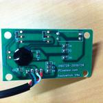
Front:
Back of the board with the diodes:
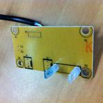
Obviously red is 5V, black is ground
The other interesting thing to note is, that they seem to also use this board in the 3-switch version of the footswitch. Hence those 2 unpopulated connectors on the board. Interestingly they can also be programmed in their provided software. It is likely that these can also be utilizied.
Footswitch i got:
http://www.pcsensor.com/index.php?_a=product&product_id=23 pedal switch:
http://www.pcsensor.com/index.php?_a=product&product_id=3Now what would be great if someone could explain how that current IR receiver registers the switching so i can understand how to modify this board for a simple push button switch.
Again, i do not just want to do the modification. I want to understand how the switching with the IR receiver works and if that is good how they have done it. Just out of curiosity. That is why i am asking here in the eevblog and not somewhere else


