OK, the background to this is that I have recently acquired a Seaward Primetest 100 PAT tester
1. I have a Primetest 50 which I use for electrical safety testing of stuff I sell on ebay
2 but I haven't been totally satisfied with it as it only has a "pass/fail" indication and doesn't do leakage current
3. The Primetest 100 displays the insulation resistance and the earth bond resistance and adds a leakage current measurement.
There was no cal certificate with the unit so I want to make sure it works properly, to check the insulation resistance/leakage measurements - I came up with this:
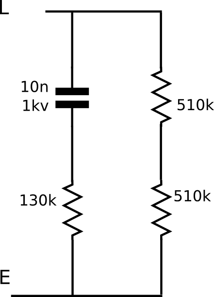
The test voltage for insulation resistance is 500V hence two 510k resistors rather than a single 1M resistor and the high voltage cap, I checked these on the Keithley and they came to just over 1.03M - the Primetest read 1.04M so that's OK.
Now, caps tend to have wide tolerances and only relatively few values are available - I wanted to have a total AC leakage current of 0.75mA as that's the regulatory limit so I thought I could trim the current by having a resistor in series.
I have a couple of multimeters capable of measuring caps, none terribly accurately, but they seem to agree that the 10nF cap is, indeed, 10nF give-or-take a few % That gives an impedance at 50Hz of 318310 ohms - add the 130k (actually 130300 ohms) plus the current through the two 510k resistors and that comes to 0.766mA.
The Primetest reads 0.8mA which although 4% high is actually in spec which is within 5%
Unfortunately this doesn't validate the PAT tester as well as I'd like - knowing the test values to only a similar tolerance to the meter spec isn't really good enough - I'd like to aim at something closer to 0.5%.
So I had the clever idea of measuring the impedance and working out the capacitance from that. So I took just the 10nF cap and 130k resistor and drove them with a 50Hz sine from my sig gen.
The SG goes up to 20V p-p (into a high impedance load, 10Vp-p into 50 ohms) which is 7.071V RMS, I measured 7.079 on the Keithley 2015.
BUT I get 5.866V rms across the cap and 2.387V rms across the resistor - I sort-of expected these to add up to 7.079V, not 8.25V
My brain does start to hurt a bit when we get to AC circuit analysis - can anyone explain the measurements without getting too mathematical? I thought I could ignore voltage/current phase differences with this set-up but perhaps not. I'm reasonably certain the readings are correct.
[1] At £30 "not working" I couldn't resist - it just took cleaning the battery contacts and the PCB pads for the front panel buttons and it was fine. Sadly while the other £30 Primetest 100 that I got at the same time responded to a similar approach it also turned out to have a
real fault as well. You win some, you lose some.
[2] Partly because I think it's a good idea and partly because I think that the Electrical Safety Regulations 1994 say you have to - I'm probably the only ebay seller who bothers though.
[3] This now gives me the conundrum that the Tek 2035 that I'm working on "failed" the leakage test. Lots of discussion on the Seaward forums about similar problems with PCs - probably due to the mains EMC filters.


