Hi guys,
What's the correct way to use a PFET for reverse polarity protection? It's to protect anLED driver, which uses a P Channel MOSFET to drive the LED, and its orientation is to have the source connected to V+, and the drain connected to the inductor which drives the LED. Also, there is just 1 pin for the Gate and 1 pin for source, whereas there are 4 pins for the Drain, as I understand the drain pins are also used to conduct heat away from the FET.
This is confusing me when it comes to the reverse polarity protection, as from the diagram I saw in afrotechmods' video (screenshot below) it shows the Drain should be connected to V+, and Source connected to the load. Is this orientation definitely correct?
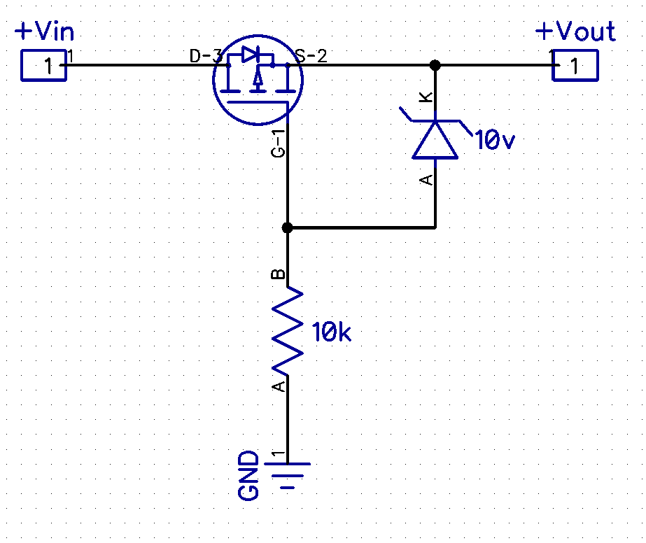
Also, I see some PFET polarity protection techniques use an additional (zener?) diode between the gate and source, along with a resistor going from Ground to Gate. Is this actually required? The input voltage in my case is 10V, and I'm looking to use
this PFET.
Any help would be greatly appreciated!
LED driver circuit in question:

PFET with diode and resistor example: