Author Topic: Mosfet Polarity  (Read 8315 times)

0 Members and 1 Guest are viewing this topic.

Offline darrenbTopic starter

  • Contributor
  • Posts: 36
  • Country: au
Mosfet Polarity
« on: November 12, 2014, 03:01:28 am »
Please see the attached image which is a simple low voltage cutout circuit created in LTSpice.

The circuit as shown works.  The comparator switches M1 on when the voltage is over 11 Volts.  M2 works for reverse polarity protection to ensure that no current flows in the circuit when connected in reverse.

What I can't figure out is why M2 has to be wired with it's source more towards the positive side of the circuit?  If I wire it with the source and drain the other way around the reverse polarity protection doesn't work.  My basic understanding (hence this in the beginners section) is that for an N channel mosfet the source connects to the negative side?

There is probably some fundamental mosfet principle I am missing.  If someone can explain this in simple terms it would be appreciated.


Offline gxti

  • Frequent Contributor
  • **
  • Posts: 507
  • Country: us
Re: Mosfet Polarity
« Reply #1 on: November 12, 2014, 03:08:29 am »
FETs are "backwards" when used in reverse-polarity protection scenarios because the body diode means they can only block current in one direction. In this application the diode points in the direction you want the current to flow: towards the negative supply. When the supply is backwards, the diode is reverse-biased and blocks current from flowing the wrong way. Turning the FET on to lower the resistance in the forward direction is then just an optimization to reduce losses.
 

Offline David Hess

  • Super Contributor
  • ***
  • Posts: 16607
  • Country: us
  • DavidH
Re: Mosfet Polarity
« Reply #2 on: November 12, 2014, 03:26:55 am »
gxti got it in one.

The body diode is not shown in the standard MOSFET symbol so I usually add it to remove confusion.
 

Offline eee

  • Contributor
  • Posts: 17
  • Country: gb
P CHANNEL Mosfet Polarity
« Reply #3 on: November 26, 2014, 09:32:29 am »
Hi guys,

What's the correct way to use a PFET for reverse polarity protection? It's to protect anLED driver, which uses a P Channel MOSFET to drive the LED, and its orientation is to have the source connected to V+, and the drain connected to the inductor which drives the LED. Also, there is just 1 pin for the Gate and 1 pin for source, whereas there are 4 pins for the Drain, as I understand the drain pins are also used to conduct heat away from the FET.

This is confusing me when it comes to the reverse polarity protection, as from the diagram I saw in afrotechmods' video (screenshot below) it shows the Drain should be connected to V+, and Source connected to the load. Is this orientation definitely correct?


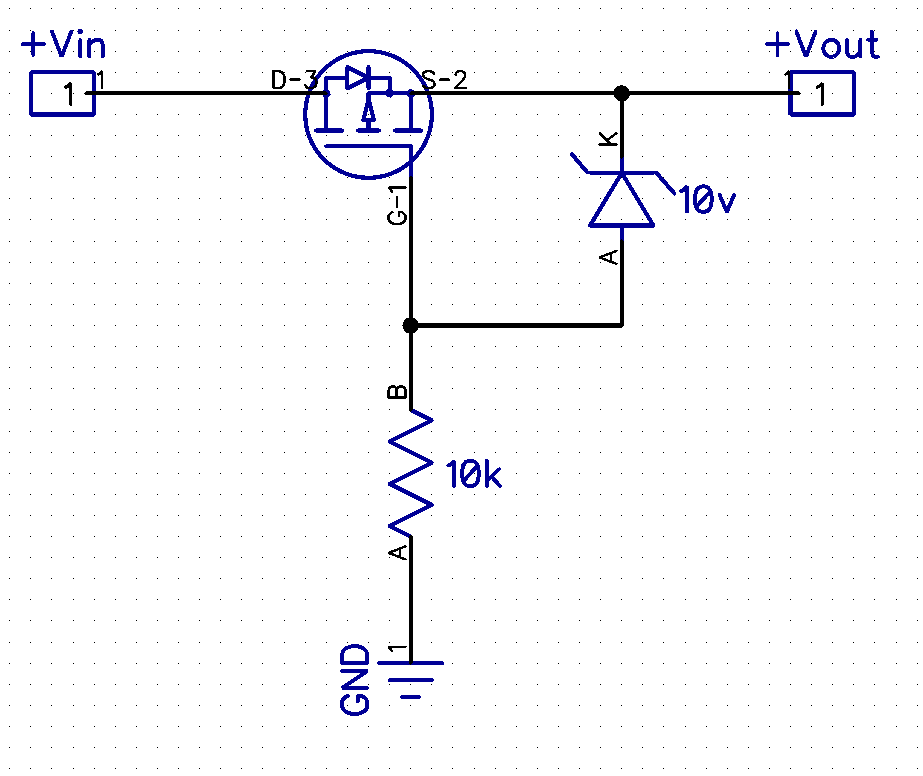
Also, I see some PFET polarity protection techniques use an additional (zener?) diode between the gate and source, along with a resistor going from Ground to Gate. Is this actually required? The input voltage in my case is 10V, and I'm looking to use this PFET.

Any help would be greatly appreciated!

LED driver circuit in question:


PFET with diode and resistor example:
 

Offline eee

  • Contributor
  • Posts: 17
  • Country: gb
Re: Mosfet Polarity
« Reply #4 on: November 26, 2014, 11:33:06 am »
I found the answer here:

http://provideyourown.com/2012/reverse-polarity-protection-circuits/

The FET is connected backwards than usual, and Vgs, the Gate-Source voltage needs to be less than its maximum rating otherwise the FET will blow, hence the diode and resistor...


Share me

Digg  Facebook  SlashDot  Delicious  Technorati  Twitter  Google  Yahoo
Smf