Author Topic: NMOS voltage level shift - 12v to 3.3v  (Read 9974 times)

0 Members and 1 Guest are viewing this topic.

Offline namluTopic starter

  • Contributor
  • Posts: 25
  • Country: 00
NMOS voltage level shift - 12v to 3.3v
« on: February 21, 2015, 06:41:28 pm »
Hello.

I drew 2 ways to shift voltage from 12v to 3.3v (from outside to FPGA). I need it in one direction only - from 12 to 3.3 and not vice versa:


Which way is better - 1 or 2? Why? Or maybe both OK?


Sent from my iPad using Tapatalk
 

Offline rob77

  • Super Contributor
  • ***
  • Posts: 2085
  • Country: sk
Re: NMOS voltage level shift - 12v to 3.3v
« Reply #1 on: February 21, 2015, 07:42:15 pm »
 :wtf:  :-//

sorry i seen many schematics during the past 3 decades but i'm lost ;)

1:  grounded drain + 3.3V voltage source in the source pin ? and the grounded drain is "Vin" ? how is supposed something with a dead short to ground be an input ?

2:  grounded gate as input ?

i'm really lost ;) try to redraw those in a more conventional way.
 

Offline namluTopic starter

  • Contributor
  • Posts: 25
  • Country: 00
Re: NMOS voltage level shift - 12v to 3.3v
« Reply #2 on: February 21, 2015, 08:34:17 pm »
Hello.

I see what is confusing. My mistake. There is a switch in the inputs, so I can toggle it in my simulation app (that's how I made sure it works).

Here it is more detailed:


Hope it's better now.


Sent from my iPad using Tapatalk
 

Offline codeboy2k

  • Super Contributor
  • ***
  • Posts: 1836
  • Country: ca
Re: NMOS voltage level shift - 12v to 3.3v
« Reply #3 on: February 21, 2015, 08:57:04 pm »
#2 is better, as it has a high-impedance input and does not load the 12V source.   #1 is low impedance.
#2 still needs a resistance on the input to protect the gate. Maybe 10k-47k.

(PS: I hate those NMOS symbols - no bulk diode shown.  It's uncommon to see that in a discrete, those symbols should be left to the IC designers, where they can do what they please with the bulk substrate)

If you only need 12 V to 3.3V level conversion, then you can also get by with just a 3.3V zener diode at the input to the FPGA. However, it's not the most efficient, as it burns power and is also low impedance and loads down the 12V source. You can use it if your source impedance is low enough that it can supply the needed current.


If you need multiple conversions, you can also use a LM339 quad comparator, with open-collector outputs. This will save some board space instead of multiple discretes.  This solution has high-impedance inputs and does not load down the 12V source input.


(image taken from here: http://wilsonminesco.com/6502primer/potpourri.html )
« Last Edit: February 21, 2015, 09:01:40 pm by codeboy2k »
 

Offline namluTopic starter

  • Contributor
  • Posts: 25
  • Country: 00
Re: NMOS voltage level shift - 12v to 3.3v
« Reply #4 on: February 22, 2015, 04:11:06 am »
Hello. Thank you. One more question.

What do you mean by resistor to protect the gate? Series resistor or pull down resistor?

If you mean series resistor:
  • why do I need one? I thought input resistance of a mosfet is very high. What do I need to protect it from?
  • why 10k to 47k value?

Sent from my iPad using Tapatalk
« Last Edit: February 22, 2015, 04:39:19 am by namlu »
 

Offline codeboy2k

  • Super Contributor
  • ***
  • Posts: 1836
  • Country: ca
Re: NMOS voltage level shift - 12v to 3.3v
« Reply #5 on: February 22, 2015, 03:11:42 pm »
I am referring to a resistor in series with the gate. It protects the gate from transients, and slows the edges for EMI.  Some people like 100 ohms. Some people like 1k to 10k. Others like 10k and more.  The proper choice depends on your system speed and how fast you want to switch the gate.   

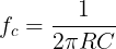
The series resistor and the gate capacitor form a low pass filter that slows the edges down, so many designers will choose a resistor that allows fast enough edges for the system switching speed (at that node), but not too fast so as to cause future EMI issues.  If you assume the gate capacitance is 5 pf to 10 pf, then you get the following cut-off frequencies for various choices of gate resistor:


R5 pf10 pf
100320 MHz160 MHz
1K32 MHz16 MHz
4.7K6.8 MHz3.4 MHz
10K3.2 MHz1.6 MHz
47K680 KHz340 KHz

Lower R values for the gate series resistor allow it to switch faster. Since 12V is often from an off-board, external event, I expected that they would be relatively slow, so I said 10k to 47k would be good. If you are switching faster than that, then choose an appropriate gate resistor that allows the edges to be fast enough for your needs, but not excessively fast as to cause unnecessary EMI.

The choice of series resistor also allows you to control the current surge into the gate, to limit the gate charging current. So if your source 12V can only provide 10 mA with a  50 mA peak, then you will want to choose a gate resistor that will limit the gate charging current as well, to stay below some reasonable value, like  25mA.  In this case, a 10k series gate resistor will limit the current to 1.2 mA max (12V/10k).  If you used a 1k resistor, that would be 12 mA, and if you used a 100 ohm, it will be 120 mA.  Those are short transient peak currents, but if your 12V supply can't handle it, you might have problems. 
« Last Edit: February 22, 2015, 03:31:54 pm by codeboy2k »
 

Offline namluTopic starter

  • Contributor
  • Posts: 25
  • Country: 00
Re: NMOS voltage level shift - 12v to 3.3v
« Reply #6 on: February 23, 2015, 09:49:04 am »
It is iCirciut app for ipad


Sent from my iPhone using Tapatalk


Share me

Digg  Facebook  SlashDot  Delicious  Technorati  Twitter  Google  Yahoo
Smf