Author Topic: Optimizing my scrap-built DC boost converter!  (Read 7732 times)

0 Members and 1 Guest are viewing this topic.

Offline vortexnlTopic starter

  • Contributor
  • Posts: 40
Optimizing my scrap-built DC boost converter!
« on: January 01, 2013, 06:12:54 pm »
Hello EEVblog! This will be my first post here  :)

I'm definitely not an electrical engineer, but just a software engineer that really likes electronics. So I've been doing this as a hobby for about 1-2 years now...

So I'm working on a DC boost converter built from scrap from old electronic boards etc. My goal is to boost a 5V USB source to a 12V source so it can drive a 12V fan at around 250mA... (unregulated)

The design I used is just the most basic design you see everywhere on the internet:
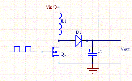


I'm driving my inductor using a 32Khz PWM signal from an Arduino, and it's working pretty good so far! There are still a few questions though regarding optimization and efficiency.

Question #1:
I'm using an IRF530N mosfet to drive the inductor, but it gets really got even after 30 seconds, this is probably due to the 60% duty cycle I'm using (this yielded the highest output voltage when connected to the fan) How can I reduce this heat? Is excessive heat normal?

Question #2:
The inductor has around 20 turns of thick wire around a toroid, could I increase the output voltage if I increase the amount of turns?

Please excuse me for my lack of experience. I just got into the field of inductance and it really interests me!  :-[

I hope the wise gods of EEVBlog can help me with my questions. Many thanks in advance,

Nick
« Last Edit: January 01, 2013, 06:29:46 pm by vortexnl »
 

Offline Kremmen

  • Super Contributor
  • ***
  • Posts: 1289
  • Country: fi
Re: Optimizing my scrap-built DC boost converter!
« Reply #1 on: January 01, 2013, 06:34:15 pm »
The boost converter transfer function is Vout = Vin * (1/(1-D)), where D is the duty cycle between 0 and 1. In practice the max voltage ratio is limited to say 4-5 times the input voltage.

IRF530N is an otherwise reasonable device for this use, but i am willing to bet it does not turn fully on if you drive it directly from an Arduino. Either change to a logic level fet such ar the IRLR3410 for example: http://www.digikey.com/product-detail/en/IRLR3410TRPBF/IRLR3410PBFCT-ND/812572, or implement a gate driver - a simple totem pole with a couple of BJTs or something like that.

The inductance of the coil is not a factor in the voltage ratio so no, you cannot influence the output voltage that way. You need to design the inductance based on other criteria such as maximum output current vs operating frequenct so as to get reasonable current ramps during the switching events.
Nothing sings like a kilovolt.
Dr W. Bishop
 

Offline jahonen

  • Super Contributor
  • ***
  • Posts: 1054
  • Country: fi
Re: Optimizing my scrap-built DC boost converter!
« Reply #2 on: January 01, 2013, 08:13:28 pm »
The boost converter transfer function is Vout = Vin * (1/(1-D)), where D is the duty cycle between 0 and 1. In practice the max voltage ratio is limited to say 4-5 times the input voltage.

Just a note, that ratio is only valid for continuous conduction mode. In discontinuous mode, the output voltage is also function of load current among other things. That is important to notice since boost converters are often used in discontinuous mode due to control loop problems with RHP zero (momentary output phase inversion) in CCM.

Regards,
Janne
 

Offline JoannaK

  • Frequent Contributor
  • **
  • Posts: 336
  • Country: fi
    • Diytao making blog
Re: Optimizing my scrap-built DC boost converter!
« Reply #3 on: January 01, 2013, 08:23:37 pm »
Sorry for OT.. but how many Finns there ar at this Forum?  8)
 

Offline vortexnlTopic starter

  • Contributor
  • Posts: 40
Re: Optimizing my scrap-built DC boost converter!
« Reply #4 on: January 01, 2013, 09:51:10 pm »
Thanks for the replies so far, perhaps I should stray on the internet a while and gather some more information about DC boost converters and inductors.


Also I'm pretty sure the 530N should be fully closed because it's getting a full 5V signal from the arduino... But still, I don't think it should get that hot with like an on resistance of like 0.064 ohms... 
« Last Edit: January 01, 2013, 10:02:45 pm by vortexnl »
 

Offline dr_p

  • Frequent Contributor
  • **
  • Posts: 309
  • Country: ro
Re: Optimizing my scrap-built DC boost converter!
« Reply #5 on: January 01, 2013, 11:57:46 pm »
If you look in the datasheet, the Gate Threshold voltage of 2...4V is the voltage at which the FET starts to conduct. It fully opens on a reasonably higher value. Evidence of this is the fact that RDS(on) is given at VGS(th)=10V. In practice it will be fully on before 10V, but most likely over 5V.

It's easy to convince yourself of this by giving it a constant 5V at he gate and measure the voltage on the inductor.
« Last Edit: January 02, 2013, 12:01:30 am by dr_p »
 

Offline svofski

  • Regular Contributor
  • *
  • Posts: 53
  • Country: ru
    • svo's interactive persuasion vehicle
Re: Optimizing my scrap-built DC boost converter!
« Reply #6 on: January 02, 2013, 12:33:09 am »
I had good and repeatable success driving IRF630's with 5V logic signals from AVR, no problems. That's probably on the margin of its working conditions, but it works.

If your inductor gets hot, the core gets saturated. You need to experiment with frequency and duty cycle: first find the duty cycle where the core does not saturate. Then you can (carefully) increase the frequency so that it has time to discharge. How hot is hot however? Can you hold a finger to it? Does it go psssffft if you you touch it with a wet finger?

I'm curious about where the Vout = 5*Vin figure comes from? If that was really so, none of my nixie clocks that need about 180V would have worked from a 9V power supply, and they happily work for years. In fact they fire up from 5V just as well.
The dark boxes are coming
 

Offline uhmgawa

  • Newbie
  • Posts: 5
Re: Optimizing my scrap-built DC boost converter!
« Reply #7 on: January 02, 2013, 12:59:48 am »

Question #1:
I'm using an IRF530N mosfet to drive the inductor, but it gets really got even after 30 seconds, this is probably due to the 60% duty cycle I'm using (this yielded the highest output voltage when connected to the fan) How can I reduce this heat? Is excessive heat normal?

I'd suspect the inductor is saturating.  Otherwise additional energy storage in the inductor would
occur yielding a higher output voltage with a duty cycle in excess of 60%.  You can verify this by
scoping the inductor current in operation to determine if the current deviates from a linear ramp.
 

Offline vortexnlTopic starter

  • Contributor
  • Posts: 40
Re: Optimizing my scrap-built DC boost converter!
« Reply #8 on: January 02, 2013, 01:26:03 am »

Question #1:
I'm using an IRF530N mosfet to drive the inductor, but it gets really got even after 30 seconds, this is probably due to the 60% duty cycle I'm using (this yielded the highest output voltage when connected to the fan) How can I reduce this heat? Is excessive heat normal?

I'd suspect the inductor is saturating.  Otherwise additional energy storage in the inductor would
occur yielding a higher output voltage with a duty cycle in excess of 60%.  You can verify this by
scoping the inductor current in operation to determine if the current deviates from a linear ramp.

What does it mean if an inductor saturates?
 

Offline vortexnlTopic starter

  • Contributor
  • Posts: 40
Re: Optimizing my scrap-built DC boost converter!
« Reply #9 on: January 02, 2013, 01:30:52 am »
Okay I just did some more testing. The 530N doesn't get that hot anymore, but just a little when powered from my 5V arduino rail. However... When powering the circuit from a 4-cell nicad battery pack charged at around 5.3 volts the mosfet stays perfectly cool. Maybe it needed a bit more gate voltage? Also the battery pack provides WAY more current as the USB source so the fan is spinning really nicely!
 

Offline svofski

  • Regular Contributor
  • *
  • Posts: 53
  • Country: ru
    • svo's interactive persuasion vehicle
Re: Optimizing my scrap-built DC boost converter!
« Reply #10 on: January 02, 2013, 01:46:34 am »
Inductor is like a capacitor. First it sucks up energy, but after some point it cannot take any more. Then it becomes basically a wire-wound resistor and low ohmmage resistors like getting hot when a lot of current is flowing through them.
The dark boxes are coming
 

Offline uhmgawa

  • Newbie
  • Posts: 5
Re: Optimizing my scrap-built DC boost converter!
« Reply #11 on: January 02, 2013, 06:02:54 am »
Okay I just did some more testing. The 530N doesn't get that hot anymore..

I'd recommend getting a scope on the circuit as from your description it seems unstable,
perhaps due to parasitics in the prototype setup.  Eg: the mosfet could be intermittently
entering high frequency oscillation which would as well cause increased switching losses.
Unsure what the rise time of the gate drive may be, but you could also try a series resistor
(5~20 ohm) to tame the slew rate.  Do you have a suitable decoupling cap between the
inductor vin and mosfet source gnd?  What sort of breadboard setup are you using?

Note assuming an ideal conversion 12V @ 250ma is 3W requiring 600ma from a USB
port which is beyond the USB 2.0 500ma limit.  80% efficiency isn't unreasonable for a
diode switched boost converter at these voltages which would up the 5V current draw to
750ma.


Offline vortexnlTopic starter

  • Contributor
  • Posts: 40
Re: Optimizing my scrap-built DC boost converter!
« Reply #12 on: January 02, 2013, 12:10:21 pm »
The Arduino PWM pin is connected to the mosfet gate using a 100-ohm resistor, the rise time of the 530N is now about 1µs which isn't that bad I think. I know I'll never drive my 12V 300mA fan using USB but the battery pack was drawing about 800mA and everything was staying nice and cool  %-B
 

Offline JoannaK

  • Frequent Contributor
  • **
  • Posts: 336
  • Country: fi
    • Diytao making blog
Re: Optimizing my scrap-built DC boost converter!
« Reply #13 on: January 02, 2013, 12:34:42 pm »
I'd like to point out that officially the USB port will only give about 100mA at 5V (0.5W).. and it's usually designed to deliver 500mA (2.5W) with negiotions between device and host. So if you are planing to make 12V output with reasonably low-efficiency homemade SMPS, be carefull of not damaging the USB.

I know there are numerous higher current variants (like tablet chargers) of USB, but those are more or less nonstandard.


Offline uhmgawa

  • Newbie
  • Posts: 5
Re: Optimizing my scrap-built DC boost converter!
« Reply #14 on: January 02, 2013, 03:29:11 pm »
The Arduino PWM pin is connected to the mosfet gate using a 100-ohm resistor, the rise time of the 530N is now about 1µs which isn't that bad I think.

One practical note is you may consider closing the loop in uC firmware to avoid overvoltage failure
should the load unintentionally be disconnected.  If the load goes missing the energy in C1 will increase
until it or the  mosfet breaks down.  You can use the atmega328's ADC to sample the output voltage
through a divider.  An added robust fail safe would be zener based clamp circuitry to shunt the
mosfet drive when the zener conducts.  I'd probably want the latter safeguard at least when debugging
the PWM / pulse skip control code.


Share me

Digg  Facebook  SlashDot  Delicious  Technorati  Twitter  Google  Yahoo
Smf