Author Topic: Potential 555 Shoot Through Problem  (Read 7432 times)

0 Members and 1 Guest are viewing this topic.

Offline Landrew2390Topic starter

  • Regular Contributor
  • *
  • Posts: 68
  • Country: us
Potential 555 Shoot Through Problem
« on: August 20, 2015, 06:55:24 am »
I was looking at the schematics for a 555 timer and noticed a possible problem.  In the attached to this post, I highlighted the output section.  Is it just me or there a possibility of shoot through in the output section when changing output states?

As a slight addition to my above question, if the shoot through exists, it is long enough to be an issue?
Oh look, a new hobby . . .
 

Offline T3sl4co1l

  • Super Contributor
  • ***
  • Posts: 21651
  • Country: us
  • Expert, Analog Electronics, PCB Layout, EMC
    • Seven Transistor Labs
Re: Potential 555 Shoot Through Problem
« Reply #1 on: August 20, 2015, 06:57:39 am »
Yes, this is a known behavior of this device.

On the order of 50-100ns duration and 100mA height, I think?

Whether it's a problem depends on your supply impedance.  Which, having numbers, can be calculated.. :)

Tim
Seven Transistor Labs, LLC
Electronic design, from concept to prototype.
Bringing a project to life?  Send me a message!
 

Offline rs20

  • Super Contributor
  • ***
  • Posts: 2318
  • Country: au
Re: Potential 555 Shoot Through Problem
« Reply #2 on: August 20, 2015, 07:02:19 am »
it is long enough to be an issue?

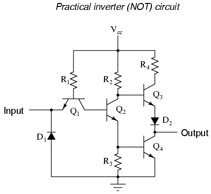
No, as evidenced by the huge prevalance of 555 chips. I presume the switching happens so fast that there's just practically no shoot through. It's worth noting that even your basic TTL not gate (with proper push-pull output) has the same """issue"""; the section you drew the rectangle around is a NOT gate after all. Also, the transistors involved are not massive power transistors; they're often rated for a short to ground for brief (by human standards) periods. Obviously having both transistors on at the same time is only half as bad as a short to ground, and it's for a period of time that is millions of times shorter. It's just not an issue. You may wish to try powering your 555 via a current sense resistor, and see the current pulses.


You may also wish to consider purchasing 555 CMOS chips, they are just faster, lower power, higher input impedance and better in every way.


Still "theoretically" capable of shoot-through, not that the current involved would be a problem, but I'm curious to see what you'd propose as a perfectly, theoretically totally shoot-through-immune push-pull output stage.

EDIT: Fixed broken image link.
« Last Edit: November 04, 2016, 11:28:39 am by rs20 »
 

Offline Landrew2390Topic starter

  • Regular Contributor
  • *
  • Posts: 68
  • Country: us
Re: Potential 555 Shoot Through Problem
« Reply #3 on: August 20, 2015, 07:28:45 am »
Thanks guys.  I'm an electrician turned electronics hobbyist.  As a result, I'm still getting a handle on certain aspects of the hobby and am having real trouble retraining myself to think in microseconds and milliamps.

I'm looking at building some stall motor controllers using 556 timers and was concerned about the chips overheating.  After reading your responses, it seems I was concerned over something that never was an issue.
Oh look, a new hobby . . .
 

Offline Cloud

  • Regular Contributor
  • *
  • Posts: 194
  • Country: si
Re: Potential 555 Shoot Through Problem
« Reply #4 on: August 20, 2015, 08:10:24 am »
I had a problem with one series of 555 (from ST) after first pulse it shorted VCC and GND until it burnt out.
 

Offline Kleinstein

  • Super Contributor
  • ***
  • Posts: 14155
  • Country: de
Re: Potential 555 Shoot Through Problem
« Reply #5 on: August 20, 2015, 08:44:53 am »
The NE555 is known to produce quite some noise / spikes on the supplies. So good supply decoupling is adviced even if the NE555 is relatively slow and may only ran at low frequency.

Compared to the TTL output stages, the NE555 can deliver about 10 times the current. TTL ICs like other fast logic need decoupling too, and usually spikes on the supply are nothing unexpected.
 

Offline T3sl4co1l

  • Super Contributor
  • ***
  • Posts: 21651
  • Country: us
  • Expert, Analog Electronics, PCB Layout, EMC
    • Seven Transistor Labs
Re: Potential 555 Shoot Through Problem
« Reply #6 on: August 20, 2015, 08:59:58 am »
The output transistors in the 555 are, in fact, quite large, nearly 2N3904 sized.  They take up almost half the die area.

555s are quite poor choices for most applications; what exactly are you trying to do?

Tim
Seven Transistor Labs, LLC
Electronic design, from concept to prototype.
Bringing a project to life?  Send me a message!
 

Offline Chris C

  • Frequent Contributor
  • **
  • Posts: 259
  • Country: us
Re: Potential 555 Shoot Through Problem
« Reply #7 on: August 20, 2015, 05:38:04 pm »
Yes, there most definitely is a shoot through.  Brief enough not to cause overheating by itself, but will still cause noise on the power supply.

You say you're going to be using 556 timers.  No matter how well you bypass the power pins, when one timer in that package switches it will momentarily disrupt the internal VCC-GND differential voltage.  This in turn affects the internal voltage divider that generates the reference points for the comparator of the other timer; and if the voltage on its timing cap was rising and sufficiently close to the 2/3 of VCC point, the new lower point will make it trigger early.

This behavior often goes unnoticed.  But not always.  When I tried to make two independently adjustable audio oscillators, I found that when set within a few hundred hz of each other, they'd suddenly lock on to each other and run at the same frequency.
 

Offline Landrew2390Topic starter

  • Regular Contributor
  • *
  • Posts: 68
  • Country: us
Re: Potential 555 Shoot Through Problem
« Reply #8 on: August 20, 2015, 05:57:21 pm »
Quote
555s are quite poor choices for most applications; what exactly are you trying to do?

I'm trying to use the 556 timer to form a low power (25mA) H-bridge.  The target application is some turnout motors for a model train layout.  I thought it might be easier to do that instead of building a H-bridge out of discrete transistors and then adding in additional parts to ensure the h-bridge doesn't switch at a bad moment.  Switching frequency might be once every 2-3 minutes.
Oh look, a new hobby . . .
 

Offline SeanB

  • Super Contributor
  • ***
  • Posts: 16276
  • Country: za
Re: Potential 555 Shoot Through Problem
« Reply #9 on: August 20, 2015, 07:24:39 pm »
Just use a capacitor of between 100 to 1000uF right by the power pins. That, along with the track resistance, will reduce the noise. Using as a bridge driver is fine, the 555 is a reasonably good driver for that, as you have the advantage of being able to set the input thresholds via the control input to interface a TTL level input with a 15V supply.
 

Offline Wim_L

  • Regular Contributor
  • *
  • Posts: 212
  • Country: be
Re: Potential 555 Shoot Through Problem
« Reply #10 on: August 20, 2015, 08:38:50 pm »
You may also wish to consider purchasing 555 CMOS chips, they are just faster, lower power, higher input impedance and better in every way.

One has to be careful with this, the CMOS variants aren't always drop-in replacements for the old 555. In some applications it may work well, in others, it will fail. The old 555 can source and sink more current from its output than some of the newer CMOS variants, and some circuits rely on that.
 

Offline Landrew2390Topic starter

  • Regular Contributor
  • *
  • Posts: 68
  • Country: us
Re: Potential 555 Shoot Through Problem
« Reply #11 on: August 20, 2015, 09:33:51 pm »
It sounds like the 555/556 timer family will work well for my application.  I've had several people recommend CMOS version if they can meet the current requirements.  CMOS won't work for this specific operation due to the current involved.  CMOS is also more expensive.  Are there any situations where I should use CMOS over bipolar or is one as good as the other with proper circuit design?
Oh look, a new hobby . . .
 

Offline rs20

  • Super Contributor
  • ***
  • Posts: 2318
  • Country: au
Re: Potential 555 Shoot Through Problem
« Reply #12 on: August 21, 2015, 12:22:41 am »
It sounds like the 555/556 timer family will work well for my application.  I've had several people recommend CMOS version if they can meet the current requirements.  CMOS won't work for this specific operation due to the current involved.  CMOS is also more expensive.  Are there any situations where I should use CMOS over bipolar or is one as good as the other with proper circuit design?
You've correctly identified two advantages of the bipolar versions: current handling and cost. The CMOS has the following advantages: much lower current consumption and much higher input impedance -- which in practice means that you can make your R's bigger and your C's smaller and still get the same time constant. This is especially useful for long time constants, where you'd need big, expensive capacitors to measure long time periods with the bipolar variants.
 

Offline Landrew2390Topic starter

  • Regular Contributor
  • *
  • Posts: 68
  • Country: us
Re: Potential 555 Shoot Through Problem
« Reply #13 on: August 21, 2015, 12:37:58 am »
A big thanks to everyone that responded to this thread.  I've been reading about electronics for years, but it's a big subject and I'm glad to have a place I can get help for stuff I don't understand.
Oh look, a new hobby . . .


Share me

Digg  Facebook  SlashDot  Delicious  Technorati  Twitter  Google  Yahoo
Smf