Author Topic: Reparing an old Roland GS-6 Digital Guitar Sound System  (Read 6925 times)

0 Members and 1 Guest are viewing this topic.

Offline obiwanjacobiTopic starter

  • Frequent Contributor
  • **
  • Posts: 988
  • Country: nl
  • What's this yippee-yayoh pin you talk about!?
    • Marctronix Blog
Reparing an old Roland GS-6 Digital Guitar Sound System
« on: December 22, 2012, 02:47:40 pm »
The following schema is the part of the unit that doesn't work.


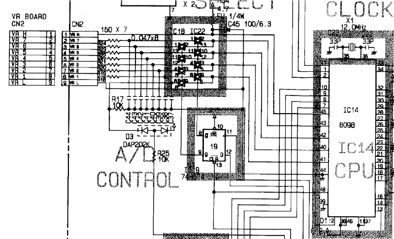
The VR board (left) contains 7 pots that are read by the processor. IC18 and IC22 (4066) switch (multiplex) these signals to 4 CPU pins (after going thru a low pass). The program monitors these levels and shows them on the display of the unit (3x7-seg) when they change. So when you turn one of the pots it displays the number (pots 1-7) and its value (0-99).

Currently the program thinks that pots 4 and 5 are constantly changing and flashes their values on the display (very annoying).

- I have checked the +5V power supply. Its fed by a 7805 and seems fine. There is less than 50mV noise on the +5V.
- On the low pass filter I can monitor the pot signals fine. ALL pots work and I can see no spikes (AC coupled various time/div).
- The flipflop sends out pretty stable switching signals - if it didn't I should also notice it on other pots.
- On the CPU pins I can see the pot levels for the two pots (6 and 7, 2 and 3 and 1) but on pin 42 I see only some small spike. The voltage collapse (or can't source the current for my 1 MOhm probe?). At that point (when pin 42 is collapsed) the annoying flashing stops (the program doesn't see the value changing) and the other pots work just fine.

- Then I lifted pin 11 from IC18 and IC20 and tested again. The problem was still there. So I though that at least the passives of the low pass were good.
- Then I lifted pin 11 from IC18 and IC20 and soldered a wire to pin 42 of the CPU. The other side of the wire I soldered directly to the input (C42) of pot 5. At that time I "thought" I had it working and that the 4066's were busted.
So I ordered new 4066's and replaced them (my first SMD replacement) but when I tried the problem was still there. Luckily I didn't make things worse either.

So now I am not sure how to continue. It could be pin 42 of the CPU that is faulty but those old 8098's are hard to come by...

Thoughts?
Arduino Template Library | Zalt Z80 Computer
Wrong code should not compile!
 

Online PA0PBZ

  • Super Contributor
  • ***
  • Posts: 5127
  • Country: nl
Re: Reparing an old Roland GS-6 Digital Guitar Sound System
« Reply #1 on: December 22, 2012, 03:03:32 pm »
Sounds like a broken PCB trace between the pins 10 of IC18 and IC22 and pin 42 of the processor.
It seems the only logical conclusion looking at what you describe.
Keyboard error: Press F1 to continue.
 

Offline obiwanjacobiTopic starter

  • Frequent Contributor
  • **
  • Posts: 988
  • Country: nl
  • What's this yippee-yayoh pin you talk about!?
    • Marctronix Blog
Re: Reparing an old Roland GS-6 Digital Guitar Sound System
« Reply #2 on: December 22, 2012, 03:12:06 pm »
That does not explain why I can't put my probe on CPU pin 42 without it collapsing - and the program stopping the flashing of the values...
Arduino Template Library | Zalt Z80 Computer
Wrong code should not compile!
 

Online PA0PBZ

  • Super Contributor
  • ***
  • Posts: 5127
  • Country: nl
Re: Reparing an old Roland GS-6 Digital Guitar Sound System
« Reply #3 on: December 22, 2012, 03:14:47 pm »
It does, when you touch it, it is no longer floating....
Keyboard error: Press F1 to continue.
 

Offline SeanB

  • Super Contributor
  • ***
  • Posts: 16284
  • Country: za
Re: Reparing an old Roland GS-6 Digital Guitar Sound System
« Reply #4 on: December 22, 2012, 03:28:49 pm »
Connect 42 to 41 or 43 and see if the inputs are the same on both channels. If so then broken track, if not sad news you need a new ( or good used) 8098.
 

Online PA0PBZ

  • Super Contributor
  • ***
  • Posts: 5127
  • Country: nl
Re: Reparing an old Roland GS-6 Digital Guitar Sound System
« Reply #5 on: December 22, 2012, 03:33:41 pm »
Quote
- Then I lifted pin 11 from IC18 and IC20 and soldered a wire to pin 42 of the CPU. The other side of the wire I soldered directly to the input (C42) of pot 5. At that time I "thought" I had it working and that the 4066's were busted.

Doesn't sound like a broken processor...
Keyboard error: Press F1 to continue.
 

Offline obiwanjacobiTopic starter

  • Frequent Contributor
  • **
  • Posts: 988
  • Country: nl
  • What's this yippee-yayoh pin you talk about!?
    • Marctronix Blog
Re: Reparing an old Roland GS-6 Digital Guitar Sound System
« Reply #6 on: December 22, 2012, 05:21:46 pm »
It does, when you touch it, it is no longer floating....

But then it should start to work, not collapse..?

Connect 42 to 41 or 43 and see if the inputs are the same on both channels. If so then broken track, if not sad news you need a new ( or good used) 8098.

I am a bit weary to connect these pins together. Basically you are shorting out any difference in pot-voltage. Can the 4066's take that?


Quote
- Then I lifted pin 11 from IC18 and IC20 and soldered a wire to pin 42 of the CPU. The other side of the wire I soldered directly to the input (C42) of pot 5. At that time I "thought" I had it working and that the 4066's were busted.

Doesn't sound like a broken processor...

That analysis (when i thought I had it working) is obviously flawed. I am not sure what I looked at in retrospect. So we should probably skip that remark altogether.

I will see if I can find any broken print tracks or bad solder joints in the vicinity.
Arduino Template Library | Zalt Z80 Computer
Wrong code should not compile!
 

Online PA0PBZ

  • Super Contributor
  • ***
  • Posts: 5127
  • Country: nl
Re: Reparing an old Roland GS-6 Digital Guitar Sound System
« Reply #7 on: December 22, 2012, 05:30:16 pm »
Just put a wire where the track should be and see if it works, it will not do any harm.
Keyboard error: Press F1 to continue.
 

Offline obiwanjacobiTopic starter

  • Frequent Contributor
  • **
  • Posts: 988
  • Country: nl
  • What's this yippee-yayoh pin you talk about!?
    • Marctronix Blog
Re: Reparing an old Roland GS-6 Digital Guitar Sound System
« Reply #8 on: December 22, 2012, 06:01:03 pm »
Yep, broken track alright. The pin 10's of the 4066 were attached fine but didn't connect to the CPU pin 42. So a little wire fixed that.

Thank you very much, I learned something new today.
Arduino Template Library | Zalt Z80 Computer
Wrong code should not compile!
 

Online PA0PBZ

  • Super Contributor
  • ***
  • Posts: 5127
  • Country: nl
Re: Reparing an old Roland GS-6 Digital Guitar Sound System
« Reply #9 on: December 22, 2012, 06:16:45 pm »
Pfew, it was more trouble to convince you than it was to find the problem  ;)

(maar mooi dat het gefixed is)
Keyboard error: Press F1 to continue.
 

Offline SeanB

  • Super Contributor
  • ***
  • Posts: 16284
  • Country: za
Re: Reparing an old Roland GS-6 Digital Guitar Sound System
« Reply #10 on: December 22, 2012, 06:23:11 pm »
Dir waar ja, maar hy is nou reg.
 

Offline obiwanjacobiTopic starter

  • Frequent Contributor
  • **
  • Posts: 988
  • Country: nl
  • What's this yippee-yayoh pin you talk about!?
    • Marctronix Blog
Re: Reparing an old Roland GS-6 Digital Guitar Sound System
« Reply #11 on: December 22, 2012, 06:44:37 pm »
Pfew, it was more trouble to convince you than it was to find the problem  ;)

And that is what I have learned.  :-DD

I can follow anybody's directions, but I want to understand it too, that was why I was discussing it.
Arduino Template Library | Zalt Z80 Computer
Wrong code should not compile!


Share me

Digg  Facebook  SlashDot  Delicious  Technorati  Twitter  Google  Yahoo
Smf