Hey guys
I've never made a complex schematic before as many aspects of electronics eluding me for many years due to dyslexia but have alway had a passion for it regardless. For much of my life I've learned by doing and observing and have a few skills that are eager for the rest of me to catch up.
My latest project is a holy grail of mine and this time I'm going to see if I can do things properly as I need some some pointers in other areas of my project and having a schematic I can show would probably go a long way in getting said pointers.
It's actually not the level of complexity that's an issue, its not knowing certain factors, one such is why parts of the same circuit are sometimes represented as seperate islands that appear not to be connected.
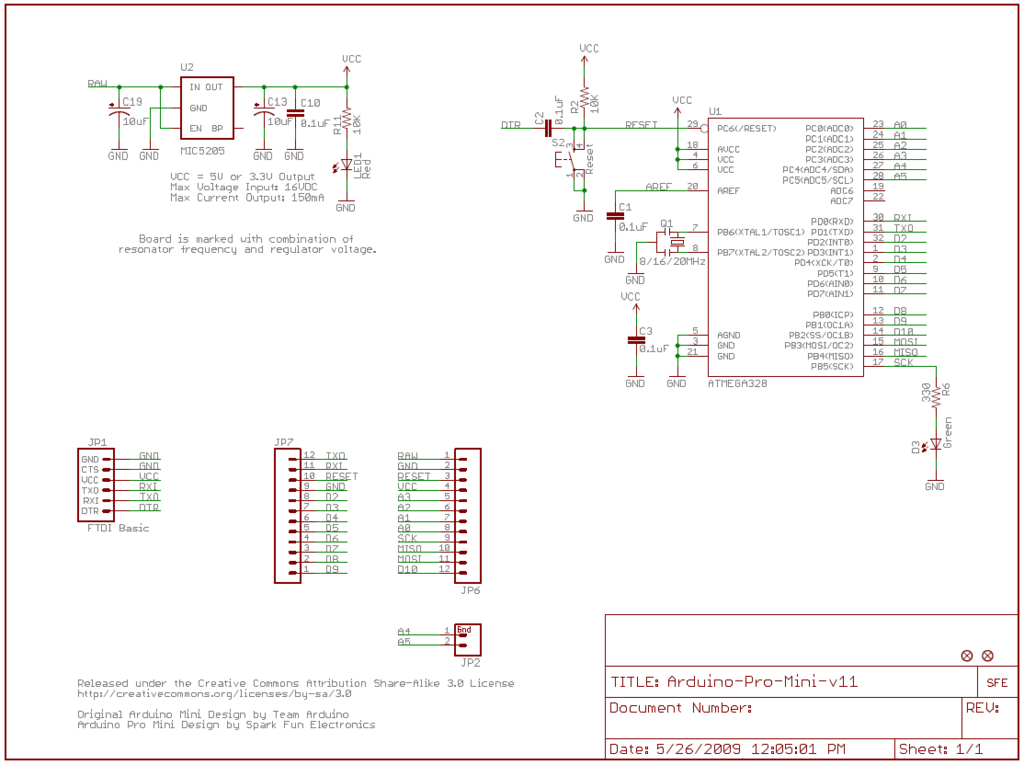
Since I'm trying to include an arduino pro mini in my drawing, I'll put the schematic for it here as its also a good representation of the islands I was reffering to:
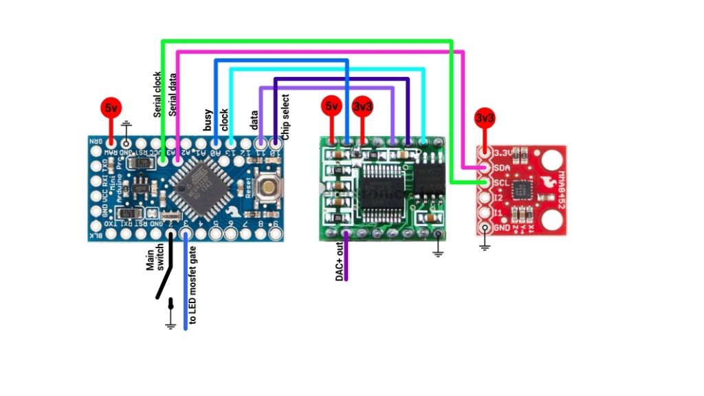
This is a diagram of the circuit I'm trying to represent in my schematic which consists of the pro mini, WT588D-16p audio playback module and MMA8452Q accelerometer breakout (yes, its for a lightsaber):
What I do know about schematic design is that positive should be at the top, negative at the bottom and connections from left to right.
The things that are bugging me most are:
As I'm using modules in real life, do I need to include all their parts in the final schematic or can I just concentrate on the functions/pins/connections I'm using and assume the others exist?
Since the modules are already pre designed circuits in their own right, could I do this simply by placing all three schematics together (but not too close abviously) and just show which of the other pins are connected between them.
That could just be me inventing an unacceptable work around though so any help would be most appreciated.


