Author Topic: Sequential LED's (like the New Mustang's Turn Signals)  (Read 17960 times)

0 Members and 1 Guest are viewing this topic.

Offline Falcon69Topic starter

  • Super Contributor
  • ***
  • Posts: 1482
  • Country: us
Re: Sequential LED's
« Reply #50 on: July 12, 2014, 04:07:21 pm »
Thank You rs20.

I will make those changes.

The SCR's are there so that the lights flash the way i want them too.  From my understanding, if they are not there, then one LED will light, turn off, move to next LED, turn off, etc.

I dont want that. I want them to turn on one by one, and NOT turn off until they've reached the end of the cycle, then all reset and repeat. Just like the new Mustangs.

Each LED will be on it's own transistor, I just have not drawn them in because that's not going to be on the circuit, but rather at the LED itself on the other end of the truck.

That 470uF capacitor is not working. It keeps the lights flashing until they dim to nothing when the turn signals are turned off. When brakes are applied, they won't stop the flashing and Light up solid until that cap has drained.  So the cap is working, as far as simulating a solid steady voltage from the flashing relay of the truck.  But, it isn't discharging fast enough.  Any cap value lower, and the flashing is just weird and is outside the adjust-ability of the Pot at pin 7 of 555. Any cap value higher, and well, the lights just flash even longer.  This could be dangerous having a delay in the lighting of the braking of the truck. Could cause accidents from behind.

So I need some help on trying to figure out how to change the flashing pulse from the turn signals themselves, into a solid steady voltage before it gets to the rest of the circuit.

Thanks in advance for your help.

Jason


Offline Falcon69Topic starter

  • Super Contributor
  • ***
  • Posts: 1482
  • Country: us
Re: Sequential LED's
« Reply #51 on: July 12, 2014, 04:36:56 pm »
I was doing alittle more research.

I found this schematic using and LM331.  A spendy little chip though compared to the 555.

Do you think this would get the job done?

I am not sure on fIN. From what I was reading on the internet, vehicle light flashing is anywhere from 1Hz-4Hz, anything higher (or faster rate) could cause seizures to some people who have those conditions. I don't have the equipment to test what rate the truck is producing.

So, on this circuit, could I place a Pot in there somewhere to adjust that so the circuit matches the frequency of the flasher IN?

Also, this is a new one for me. What is that 5k resistor (RS) with that arrow through it.  Is that another way of drawing a potentiometer?
« Last Edit: July 12, 2014, 04:38:34 pm by Falcon69 »
 

Offline rs20

  • Super Contributor
  • ***
  • Posts: 2318
  • Country: au
Re: Sequential LED's
« Reply #52 on: July 13, 2014, 02:57:56 am »
That's a perfectly legitimate application of an SCR, but I think in this case it'd be more common to use SR flip flops. An SR flip flop is a device with two inputs: S and R. There's also one output called Q (there's almost always a complementary inverse-of-Q output as well). If S goes high, Q gets Set high. If R goes high, Q gets Reset low. If both R and S are low, Q remembers its previous state.  So wire S to the output of the 4017 that decides when it should turn on, R to whatever signal should cut it off, and wire Q directly to a simple, single transistor for each LED. Bonus: if you're using NAND gates for anything, you can make an SR flip flop from just two NAND gates (see google image search for "SR flip flop" to see how, beware though: the NAND variant of the circuit takes active low inputs, so Q gets set when S goes low, etc.)

Alternatively, perhaps you don't need a stateful (the behaviour of a thyristor and an SR flip flop depends not only on current inputs to the device, but its history, so it's said to be "stateful" or it "maintains state") solution. Can't you just say that led 3 is on if output 3 of the 4017 is on, led 2 is on if output 3 OR 2 is on, and led 1 is on if output 1 OR 2 OR 3 is on? This is just a couple (yes 2, not 3) OR gates, but I'm not sure if it's exactly the behaviour your after -- not sure if you want Leds 2 and 3 stay on even as 4017 continuously loops around.

I don't see brake lights as an output to your circuit, how is your circuit having any influence on brake lights? I feel like you should leave your brake wiring untouched, and just tap off a signal as a high-impedance logic input. I don't think LM331 is the right choice. An RC circuit like in my diagram, or a 555 in monostable single-shot mode, will both work just fine. Whether your subsequent logic a) is not interfering like Q3 is and b) is correctly making use of those signals is another question. Looking at your circuit, you have 470 microfarads with a 22 kilohm resistor taking it down, which works out as a time constant of over ten seconds (google calculation), so it will think the turn indicator is still on for 10-20 seconds after it's been turned off. A time constant of 0.25 to 2 seconds or so seems more appropriate.

If you switch over to using separate logic and power sections, you'll be able to ask much better questions -- "the turn signal is turned off, yet the very next NAND gate is outputting as if it's still on", instead of "my brake lights aren't coming on". Much easier for us to diagnose, much easier for you to understand and diagnose yourself too! Stick a little LED somewhere in the circuit (but not on the RC circuit itself because that'll spoil it) that indicates whether the turn signal is active or not -- that way you can debug that issue in isolation.

Yes, that resistor with an arrow through it is a variable resistor. Technically it's only called a potentiometer if it has three terminals. If you short together the middle pin with one of the outer pins of a potentiometer, you end up with a two-terminal device called a variable resistor and it has that symbol you see.
 

Offline Falcon69Topic starter

  • Super Contributor
  • ***
  • Posts: 1482
  • Country: us
Re: Sequential LED's
« Reply #53 on: July 13, 2014, 06:22:42 am »
thank you rs20

good ideal on the led's to indicate which switch is on.  I will do that.

So shorting pin 2 with 1 or 3 on a three terminal potentiometer makes it a variable resistor and no longer a potentiometer. Thank you, that makes sense to me. Flip Flops Are one device I have yet to play around with. I will need to research into them and figure out how they work.  But sounds like a good idea.

On another note, I found out why I have been having so much problems with the circuit, and I think today I figured it out. Tomorrow I will finish the entire breadboarding and wire it up to the truck and see how it works.

The Problem I found today, and think I have fixed, is that when the left (or right) turn signal is on, the wire I have tapped into at the switch itself, pulses as the relay pulses, and then onto the lights to make them flash. Then I realized that when I then turn on the Hazard switch, the frequency of the pulses of the turn signal also changes.  And that is where the big problem is.  That Hazard flashing relay somehow is feeding through the turn signal flashing relay. The left (or right) turn signal and the Hazard switch use the same wire.  So, this is another problem I seem to have run into today when trying to make the Missing Pulse Detector circuit work. I get the pulse of the turn signals working just fine, spitting out a steady 12 volts, but, then I turn on hazards, and no more steady 12 volts, and vice versa.

But, I believe I have made it work today; after many hours of trial and error with resistor/capacitor changes.  I will test it on the breadboard tomorrow.  I hope it works.

And you mentioned the operation of the lights, this is how I want them to operate when the hazards or turn signals are on:

Flash - LED1 ON
         - LED2 OFF
         - LED3 OFF
Flash - LED1 ON
         - LED2 ON
         - LED3 OFF
Flash - LED1 ON
         - LED2 ON
         - LED3 ON
Flash - Resets the cycle.


Today, I had my nephew placing the jumpers and components on the breadboard.  So a 1 hour job turned into like a 4 hour job.  I was teaching him how to read the schematic and how to place the jumpers.  He was having fun and getting excited about how things worked. I don't think he exactly understood about the part where I was making him highlight the traces on the schematic as he was placing the parts.  Maybe I should have let him get an hour into the project first, and watched his frustration as he was trying to remember which parts he placed and where. Then, just maybe, he'd understand the importance of it.  LOL

I hope this thing works tomorrow.  If it does, I'll post up the schematic that worked for me, maybe it can help others, or maybe with help, can implement changes to make it less power drain.  I haven't quite got into working with logic gates or flip flops, but I'm learning.

Jason
 

Offline Falcon69Topic starter

  • Super Contributor
  • ***
  • Posts: 1482
  • Country: us
Re: Sequential LED's (like the New Mustang's Turn Signals)
« Reply #54 on: July 18, 2014, 06:45:13 pm »
SO, I couldn't get the Missing Pulse Detector working, SO I am tryin a new approach.  It seems that when I set the resistor/capacitor to work with the turn signals, it is fine, but when the Hazards are turned on, it goes all screwy again.  It seems that the Turn Signal and Hazard flash (pulse) at a different rate on his truck.  So I can't get it tuned correctly.

So, I am trying to use a relay to do it. 

Here is the new schematic, but I am having trouble.  Doesn't seem as if the transistors are all turning on correctly.

Ultimately, what I am trying to do with the relays is, the bottom relay takes the signal from the turn signals and hazards and turns it into a steady pulse. The 1000uF capacitor keeps the current flowing to keep the relay on.  However, at this time, I only had two 100uf Capacitors to work with and placing them in parallel is not enough to keep the relay active.  So I'm hoping the 1000uF is enough.  Also, when the relay is off, it activates the transistors for the brake/park to allow them to turn on.  I don't want the brake and park to go on while the flashers are on. The top relay is to deactivate the park lamp when the brakes are applied. No sense in having both on at same time, wasting current or supplying too much current to the LED's.

I know there are lots of transistors here, but I think if I have dawn it right, they all serve their purpose.

It was suggested to change the schematic to allow the transistors to turn on correctly.  That is the second schematic I have drawn up.  one single 10k resistor to turn on all transistors when the bases are tied together did not provide enough current to do so.  The consensus was to divide the 10k into how many resistors (10k resistor divided by 4 transistors = 2.5k resistor) and use a 2.5k resistor, which should allow enough current to each transistor to turn on. It was also suggested that placing a 10k resistor at each transistors base was probably a better idea.

Will the second schematic work properly?  I can hear the relays switch, but I get no LED's turning on (or sequencing) except for the first LED going into the bottom relay.

Thanks in advance for your input.
Jason

EDIT:  I know that everything from the SCRs to the right work correctly, as in the previous circuits, the sequencing of LED's worked as intended.  I just changed everything before that in these next two schematics.
« Last Edit: July 18, 2014, 06:46:56 pm by Falcon69 »
 

Offline Falcon69Topic starter

  • Super Contributor
  • ***
  • Posts: 1482
  • Country: us
Re: Sequential LED's (like the New Mustang's Turn Signals)
« Reply #55 on: July 18, 2014, 06:49:15 pm »
Oh, I also have a question.

The Diode between pins 86 and 85 on the relays.  I understand that is needed to prevent flyback when the switch is turned off.  My question is, what amp/volt rating do those need to be?  Right now, I have them at 400v 3A.  I think that is overkill, and they are awfully large to place on the PCB.
 

Offline idpromnut

  • Supporter
  • ****
  • Posts: 613
  • Country: ca
Re: Sequential LED's (like the New Mustang's Turn Signals)
« Reply #56 on: July 18, 2014, 10:43:14 pm »
I may have missed this piece of info, but does your circuit have access to a steady 12v other than the turning flasher?
 

Offline Falcon69Topic starter

  • Super Contributor
  • ***
  • Posts: 1482
  • Country: us
Re: Sequential LED's (like the New Mustang's Turn Signals)
« Reply #57 on: July 18, 2014, 10:49:43 pm »
yes, it is connected to the battery of the truck. Steady voltage.  I think with the engine running, it puts out 12.8 volts and could go up to 14.4volts.

But, the switch for the turn signals puts out a pulse of 12 volts. The wires to and from the turning switch all pulse. The flashing relay is the culprit.  I can't disconnect that, otherwise the front blinkers won't flash, unless I do a separate circuit for that, which I am trying to avoid.
 

Offline rs20

  • Super Contributor
  • ***
  • Posts: 2318
  • Country: au
Re: Sequential LED's (like the New Mustang's Turn Signals)
« Reply #58 on: July 19, 2014, 02:20:15 am »
The RC/555 monostable circuit will work, it's much easier to debug that than going down any other path. It does not need to be tuned precisely; it takes pulse gaps of any length and shorter and fills them in. So if you're trying to catch two different pulse trains with difference frequencies, "tune" it to the slower one, and you get the faster one for free. You should develop the RC circuit as a *separate* block, get it working perfectly, and then it's a black box you can trust -- or if it does fail, you know it's the surrounding circuitry that breaking it. Logic gates take away this concern about breaking other parts of the circuit because they have a huge input impedance (i.e., they claim tiny amounts of current) and can drive their outputs quite strongly. This is in contrast to BJTs, which provide output current in proportion to their base current, which makes biasing them to be strong enough to drive their output without breaking their input a non-trivial task.

I don't understand what the relay is supposed to be achieving here. Relay coils have low resistance, the coil of the relay is going to drain that capacitor in a fraction of a second, relay coils are not high-impedance devices. Use a high value resistor and a logic buffer that doesn't drain the capacitor (i.e., NOT a BJT), and hey look we're back to the RC circuit.

How are the turn signals and hazard signals just coming in through the same wire? Have you just shorted them together??

You're switching the ground of the CD4017!? Run! Run away!

At the risk of sounding like a broken record, this circuit is about 3 times more complicated now than it would be with clearly separated logic and LED drive sections. If you can get it to work like this, I take my hat off to you.


Offline Falcon69Topic starter

  • Super Contributor
  • ***
  • Posts: 1482
  • Country: us
Re: Sequential LED's (like the New Mustang's Turn Signals)
« Reply #59 on: July 19, 2014, 04:09:37 am »
rs20

I've tried using a logic circuit with another circuit i am working on for a different purpose.  I can't get it working. Simulation shows it works, but when breadboarding, it does not. So I don't know how to work with logic gates either.

The problem with 'tuning' the 555 to work with the slower pulse is that pulse works fine (i.e. the Hazards), but when I turn the blinker on and off, then it stays on too long afterwards and there is a delay in the brakes when applied. That's dangerous.

I don't understand half of what is being said here I guess. I'm more of a visual person, if I can see it drawn, or see it work in a video, then I can understand for the most part.  I try to understand. I've spent over 2 weeks trying to make this circuit work. Been spending every waking moment trying to research and look for stuff on the net to help me understand.

Even if I could get logic gates to work, I still have to deal with the problem of the flashers.

Yes, it is one wire. Flip the switch for the left turn signal, you get a pulse through the wire that is tapped into at the switch. You flip on the hazards (whether turn signal switch is on or off, doesn't matter), you get a different pulse through that same wire, only difference is, now you get that pulse through TWO wires, the left and right turn signal switch.

So the only wires connected to the collector of the transistor should be the cathodes of the SCRs? The grounds for the 4017, 555, caps, etc. should be grounded normally?
 

Offline idpromnut

  • Supporter
  • ****
  • Posts: 613
  • Country: ca
Re: Sequential LED's (like the New Mustang's Turn Signals)
« Reply #60 on: July 19, 2014, 01:36:03 pm »
The engineer in me says that it is time to step back and start at the beginning. Re-write your goals/requirements, draw up a thorough wiring diagram of the original truck's circuits, measure voltages to ensure you know what is connected to where and put it on the diagram. Measure any signals that you will need, such as the flashers (both voltages and blinking frequencies).
After this, then you can both post that info here to help us get a better understanding of the original system and you can start designing a block diagram of the circuit that you will need to get the turn signal effect you are looking for.
 

Offline rs20

  • Super Contributor
  • ***
  • Posts: 2318
  • Country: au
Re: Sequential LED's (like the New Mustang's Turn Signals)
« Reply #61 on: July 19, 2014, 01:41:48 pm »
I must confess that I don't know what precise behaviour you've been wanting (although I'm 100% sure that every comment I've made is correct regardless of the details I haven't understood). If you want the brake light to always take precedence (a concept I heartily encourage), then you should make the logic consider the state of the brake light as more important than the turn signal/hazard light. What you want to happen when the turn signals AND brakes are on at the same time is an explicitly decision you make as a circuit designer, not something that falls out from the design that you have to live with and work around. The first step is to draw up a logic table (it's not as hard as it sounds) which describes how the LEDs respond to the various inputs, and which inputs take precedence over other inputs. For example,


        INPUTS                       |     OUTPUTS
Brake   Park     Hazard/Turn Signal  |      LEDs
--------------------------------------------------------------------
 On       X             X            |      Off
 Off     On             X            |      Off
 Off     Off         Flashing        |      Off
 Off     Off           Off           |   Cycling as described

( X means "Don't care")


So, for instance, this means that if the brake is on, the LEDs should be off, regardless of what the hazard, turn or park signals are doing. If the brake is off, but the park signal is on, the LEDs should also be off. Etc etc. If you could please correct this table to accurately state your intentions, then it will certainly clarify things for me, and maybe allow me to recommend specific fixes for your circuit (or indeed, as idpromnut just posted, we can think about taking what you've learned and doing a quick do-over based on distinct blocks).

Also, please clarify that you are leaving the brake lights, turn lights, etc etc all plugged in, and that you are only adding wires to these lines to your circuit to control 3 additional LEDs that are completely separate from the traditional stop & turn lights you find on any car.


Offline Falcon69Topic starter

  • Super Contributor
  • ***
  • Posts: 1482
  • Country: us
Re: Sequential LED's (like the New Mustang's Turn Signals)
« Reply #62 on: July 19, 2014, 03:35:21 pm »
I am leaving the factory wiring in the truck for two reasons.

One: In case he puts the bed of the truck back on, he can simply just plug his factory lights back in.
Two: Messing with the factory wiring harness could mess up the front lights, as well as the hitch lights for towing.

I am only tapping into the factory harness to get the 12 volts from the switches themselves.

I use a Snap-On 12v test light. It plugs into the cigarette lighter of the truck.  It has two built in LED's, one is red, other is green.  When it senses ground, it changes to green only, power it changes to red.  Pretty simple.

The wire from the brake switch is putting out 12 volts, ± 1 volt. When it is off, there is no signal, it does not alternate back to ground. (my test light shows both red/green LED's on inside it, indicating as if the wire was never hooked up to ANYTHING.)

The wire from the Park Lamp is putting out 12 volts, ± 1 volt. When it is off, the test light changes to green, indicating it is to ground.

The wire from each turn signal is putting out 12 volts, ± 1 volt, however, it alternates from voltage to ground. I don't know the frequency of the pulse, but from what I've been reading, it is about 1.5 hz (90 flashes per minute). I do not have a scope to test that. When the switch is off, the test light shows the wire then goes to ground. When the hazards are turned on, both the left and right turn signal alternate from power to ground, however, it is at a slower frequency, maybe at 60 or 70 Hz.

Rs20, this is what I am after:


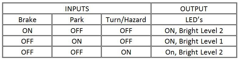
The table above is per side, left or right.  For instance, when the turn signal is on the left, and brake is applied, the right side will have the brake light, but the left side will be flashing.

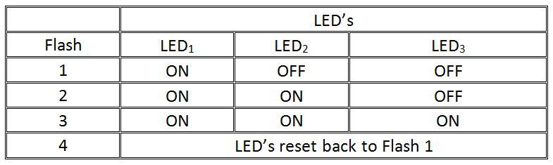
The way I want the LED's to work when the turn signal/hazard is activated is like this:


I played around with this last night:


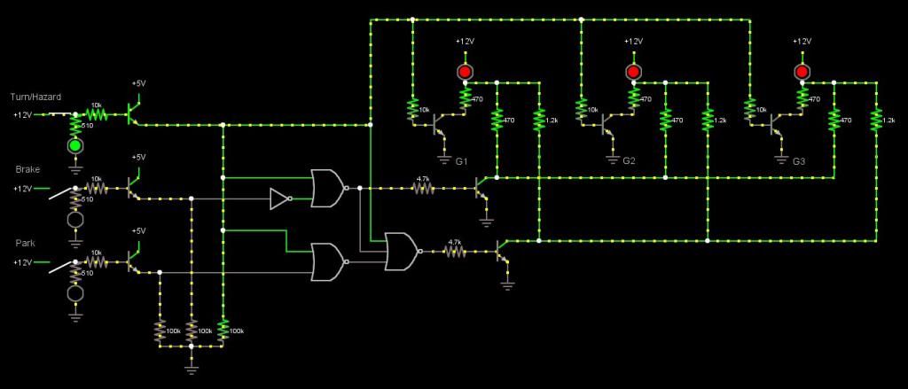
G1, G2, and G3 would be connected to the Anodes of the BT169's in the original circuit.

I would still need to figure out how to change the pulse into a steady for the Turn/Hazard.

This circuit would use one Inverter, two NOR gates, and one 3-input Nor Gate.

I would still need the 4017 and 555 and the BT169's to do the sequencing.

The 470 resistors would not be needed and the 1.2k need to be reduced, as the LED assemblies have them built in.  I just needed those values for the simulation using single LED's for the visual. So please disregard those.

Jason


Share me

Digg  Facebook  SlashDot  Delicious  Technorati  Twitter  Google  Yahoo
Smf