Author Topic: simple relay circuit - improvements?  (Read 3798 times)

0 Members and 1 Guest are viewing this topic.

Offline snailFuryTopic starter

  • Contributor
  • Posts: 13
  • Country: 00
simple relay circuit - improvements?
« on: February 01, 2014, 07:19:49 pm »
Hi All, I've been working on a simple relay circuit. I've attached a block diagram I did in google draw. I've built the circuit and it works. I drew it afterwards by looking at my (ghastly) prototype board I soldered up, so hopefully I got it right! So what I am wondering is, am I missing anything essential like a capacitor to smooth things out, or something else to promote longevity of the components. The arduino and 12V supply are coming from wallwart transformers.

My understanding of this circuit is:
arduino triggers the npn which triggers the relay which controls "current"
the diode is there for flyback protection
the led is just and indicator for when the relay switch is closed

Basically, does this circuit need to be improved?
Can it be replicated on a single board?
Other considerations?

thanks!
 

Offline Hideki

  • Frequent Contributor
  • **
  • Posts: 256
  • Country: no
Re: simple relay circuit - improvements?
« Reply #1 on: February 01, 2014, 07:38:03 pm »
No, you don't need anything else, but the 100 ohm LED resistor seems rather low if you're driving a normal led from 12V.

You do however need a common ground connection to the Arduino, which I assume you have, since it works. It is however not drawn in, so we have to use our psychic powers to guess what you're really doing :)
 

Online mariush

  • Super Contributor
  • ***
  • Posts: 5029
  • Country: ro
  • .
Re: simple relay circuit - improvements?
« Reply #2 on: February 01, 2014, 07:42:53 pm »
The 22kohm seems quite high to me - make sure the transistor opens enough. 
For example, let's say the relay needs 100mA to work, and the npn transistor has a minimum hFe of 80 and an average of 100. You need the transistor to let 100mA flow. 
If the transistor has hFe of 80-100, then be conservative and assume the hFe could be as low as 70 in some cases so that means that to have 100mA pass from collector to emmiter, you would need about 1.5mA at the base (1.5 x 70 = 105mA)

To get the resistor value ... you have ohm's law  V = I x R  but don't forget there's a 0.6v drop on the npn transistor so  5v arduino - 0.6v drop  = 0.0015 x R => R = 4.4 / 0.0015 = 2933 ohm.  I would just go with a 2700 ohm resistor and allow up to about 2mA on the base.

The pdf is not clear about how that diode is connected.  The protection for the relay voltage is like this:
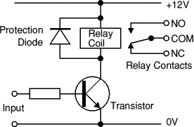


If you want the led to light up when relay works, connect + before after relay at 12v and the negative after relay, before npn transistor.  12v ---> resistor ---> + led - ---> after npn. Choose a resistor accordingly.  Led has about 2-3v, and you want to let about 20mA go through the led so again v = i x r  = >  12v -3v = 0.002 x R => R = 9/0.020 = 450 ohm  so you can pick 470 ohm or something around that value, whatever is convenient. 10-20mA will be plenty bright, so no need to be super exact with the resistor, but 100 ohm will allow too much current (maybe about 70-100mA through the led) and will burn it.

edit : corrected the led paragraph, i wrote something stupid before.
« Last Edit: February 01, 2014, 07:58:39 pm by mariush »
 

Offline snailFuryTopic starter

  • Contributor
  • Posts: 13
  • Country: 00
Re: simple relay circuit - improvements?
« Reply #3 on: February 01, 2014, 08:00:54 pm »
Yes mariush, you are right, I mistyped that - it is actually a 2.2K resistor.
And the bar on the diode is facing back toward 12V.
And regarding the LED, the 100ohm resistor is what was recommended for lighting an LED via an arduino tutorial so I just went with it. It looks nice and bright, but maybe too bright,...I'll look into that...
 

Offline Fabiusp98

  • Contributor
  • Posts: 23
  • Country: it
Re: simple relay circuit - improvements?
« Reply #4 on: February 01, 2014, 08:02:59 pm »
It won't be better if you simplify the circuit by getting rid of the transistor and use a 5v relay?
 

Offline snailFuryTopic starter

  • Contributor
  • Posts: 13
  • Country: 00
Re: simple relay circuit - improvements?
« Reply #5 on: February 01, 2014, 08:25:39 pm »
Yes I think that it might be a possibility to use a 5V relay. I guess I didn't because I wanted to practice using transistors. Also, is a 5V relay limited by the amount to current you can pass? Might be a design limitation down the road as far adaptability
 

Offline IO390

  • Regular Contributor
  • *
  • Posts: 232
  • Country: gb
Re: simple relay circuit - improvements?
« Reply #6 on: February 01, 2014, 10:14:01 pm »
I would always use a transistor to drive anything much more than a LED with an arduino. 20mA from the o/p pins is about the max it can do.
 

Offline electronics man

  • Frequent Contributor
  • **
  • Posts: 686
  • Country: gb
Re: simple relay circuit - improvements?
« Reply #7 on: February 01, 2014, 10:31:00 pm »
I think it would be better to use a MOSFET than an npn as you won't need any resistors on the gate. And it thing you should start to draw schematics Instaid of. Block diagrams for this sot of thing
follow me on twitter @get_your_byte
 

Offline Psi

  • Super Contributor
  • ***
  • Posts: 9951
  • Country: nz
Re: simple relay circuit - improvements?
« Reply #8 on: February 01, 2014, 10:34:41 pm »
The 100ohm resistor is what was recommended for lighting an LED via an arduino tutorial so I just went with it. It looks nice and bright, but maybe too bright,...I'll look into that...

The arduino tutorial is recommending 100ohm for driving a typical
LED from the arduino which is 5 Volts.
5 volts and a typical 3V led = 2V left.   2V / 100R = 20mA, which is a normal amount of current for an LED

12V and typical 3V LED = 9V left.  9V / 100R = 90mA   :scared:

So to keep the LED from exploding you should use a 470ohm resistor.

(Or you could use a bigger LED rated for 90mA and keep the 100R)
« Last Edit: February 01, 2014, 10:36:44 pm by Psi »
Greek letter 'Psi' (not Pounds per Square Inch)
 

Offline snailFuryTopic starter

  • Contributor
  • Posts: 13
  • Country: 00
Re: simple relay circuit - improvements?
« Reply #9 on: February 01, 2014, 11:23:54 pm »
Electronics man - what free schematic program would you recommend I use? And thank you for the mosfet suggestion

Psi - I stand corrected. I think my power supply is putting out a little less than 12V, but I take your suggestion regarding the resistor
 

Offline Rerouter

  • Super Contributor
  • ***
  • Posts: 4694
  • Country: au
  • Question Everything... Except This Statement
Re: simple relay circuit - improvements?
« Reply #10 on: February 02, 2014, 12:00:59 am »
If you want to get boards made i would say kicad, (its library editor is not the most obvious thing in the world to start using, but its good once you get the hang of it)
 

Offline sdg

  • Regular Contributor
  • *
  • Posts: 67
  • Country: fr
Re: simple relay circuit - improvements?
« Reply #11 on: February 02, 2014, 11:31:41 am »
I think it would be better to use a MOSFET than an npn as you won't need any resistors on the gate.

A MOSFET gate will draw I=Ciss*dVDG/dt. That can be enough to fry the output stage of a CMOS IC.
Besides, a current-limiting resistor on the gate also offers some protection against ESD. Might be of some benefit if the MOSFET is on an Arduino shield and the shield is left unconnected.
--
 -sdg


Share me

Digg  Facebook  SlashDot  Delicious  Technorati  Twitter  Google  Yahoo
Smf