Author Topic: Powering relay with 555 timer  (Read 5139 times)

0 Members and 1 Guest are viewing this topic.

Offline SkipMorrowTopic starter

  • Contributor
  • Posts: 17
  • Country: us
Powering relay with 555 timer
« on: August 04, 2017, 02:50:29 am »
I am trying to power a relay with the output of a 555 timer circuit. It will be powered by three D-Cell batteries, so a little over 4.5V. I picked a 1.5V relay because I thought I could just put a resistor in series with the coil to reduce the voltage, but that doesn't seem to be working. I can hook up my power supply to the relay coil and it will cycle correctly. I have installed a 1N4148 diode in reverse across the coil. Like I said, when I try to cycle the relay with my power supply, it works fine. But when I try to cycle it with the 555, no joy. The resistance of the coil is about 16 ohms, so I thought if I went with a 37 ohm resistor, the coil would see a little less than 1.5 V, but that didn't work. I have also tried smaller and larger resistors, again with no luck.

It seems that most of the 555 circuits using relays online use 12 or more volts with their 555s. I don't have that option. I definitely need a relay of some sort because it is going to control an arduino and some LED strips.

Any idea what I am missing?

Skip
 

Offline Nusa

  • Super Contributor
  • ***
  • Posts: 2416
  • Country: us
Re: Powering relay with 555 timer
« Reply #1 on: August 04, 2017, 02:59:39 am »
16 ohm coil at 1.5 volts probably needs nearly 100ma to operate. Which is pushing the limit of what the 555 will give you at 4.5v.
 

Online MK14

  • Super Contributor
  • ***
  • Posts: 4536
  • Country: gb
Re: Powering relay with 555 timer
« Reply #2 on: August 04, 2017, 03:07:17 am »
EDIT: You ideally should have chosen a relay with a higher coil voltage. That would have increased the coil resistance, and hence reduced the current needed to power the relay's coil.
Since you plan on running it at 5 volts, then a coil voltage of around 4 volts, would make more sense (assuming the output driver voltage drop is no more than a volt).
I.e. it needs to be the supply voltage minus the expected voltage drop across the output driver. Which for a 555 timer is fairly significant (e.g. 1 volt, depending on output load current, and which type of 555 timer you are using).

As the other poster says, the 555 only gives a limited output current. Which does not seem to be enough, for your relay.
If you use a transistor, on the output of the 555 timer. It can pass a lot more current, for your relay coil.
Example to give you a basic idea, NOT the exact circuit you need (just to show how to connect the transistor up):

« Last Edit: August 04, 2017, 03:39:29 am by MK14 »
 

Offline Ian.M

  • Super Contributor
  • ***
  • Posts: 12856
Re: Powering relay with 555 timer
« Reply #3 on: August 04, 2017, 03:40:38 am »
A bipolar 555's output doesn't go rail-to-rail, and its output high can drop as musch as 2v from the rail with a 100ma load.  Your total load of 53R (relay + resistor) was probably drawing a bit less than 50mA with the output dropping about 1.5V from the rail, and obviously that was below its pull-in current.   To make the voltage more predictable you need to reduce the load on the  555 output, and the best option would be to use a NPN transistor, emitter to ground, relay + 30R resistor between its collector and Vcc, and with a 240R resistor between its base and the 555 output for about 10mA base drive so its fully saturated when on. Edit: see circuit Bill just posted. If the relay was originally between out and Vcc, use a PNP transistor, emitter to Vcc, relay + resistor between its collector and ground. 

However the whole design is moot as with only a three cell supply, the 555 will crap out on you due to low voltage long before the batteries are drained.  You really need 4 cells as a minimum to power the 555, and even that will drop below the 555's 4.5v rated minimum with a third of the battery capacity still remaining.  A 5V relay would probably be a fairly good match, if you use the external transistor as I suggested.
 

Online MK14

  • Super Contributor
  • ***
  • Posts: 4536
  • Country: gb
Re: Powering relay with 555 timer
« Reply #4 on: August 04, 2017, 04:00:03 am »
EDIT: DON'T increase battery voltage. I mean use the relay coil, which will use the least current, but still work with whatever battery voltage you are using.
Ideally you want to use as high a coil voltage relay, that you can get away with. Because it will have a much higher coil resistance (usually, for the same relay series) and hence use much less current, and so give you a much longer battery life.

In the longer term, batteries may cost more than the cost of buying a more suitable relay.

In other words, get as high a coil resistance relay as you can, which will satisfy the requirements for your project. The higher the resistance, the lower the current and hence the longer the battery life.
Your requirements will be coil voltage and max current limit of relay.

EDIT:
Ian.M's comments about your 4.5V battery voltage being too low or very marginal for the bipolar NE555, are quite right.

If you insist on using 4.5V batteries, you could use a CMOS 555 timer. Which can go down to something like 1.5V operation (exact minimum voltage depends on which version you use). But it has a weaker output, so the extra output transistor, would be much more important. (unless the relays coil uses a small enough current, to be usable directly).
« Last Edit: August 04, 2017, 04:57:17 am by MK14 »
 

Offline Ian.M

  • Super Contributor
  • ***
  • Posts: 12856
Re: Powering relay with 555 timer
« Reply #5 on: August 04, 2017, 04:36:57 am »
The problem is: doubling the battery voltage typically doubles the cost of them AH for AH. 

There is no net benefit from the relay's lower current as if you want to halve the current, it needs the same number of ampere turns to operate, and electrical grade copper is the same resistivity, so packing twice as many turns on the bobbin will halve the overall wire cross section and slightly more than double the resistance due to the extra space wasted by more enamel insulation, so it will need a bit more than double the voltage.

Assuming the relay is double the voltage it will therefore be slightly over half the current and you are now taking a bit under twice as long to use up twice as many batteries.   That's a clear bust but the initial investment is higher so depending on how much of your spending money you tie up, there's lost opportunity cost as well
 
The following users thanked this post: MK14

Online MK14

  • Super Contributor
  • ***
  • Posts: 4536
  • Country: gb
Re: Powering relay with 555 timer
« Reply #6 on: August 04, 2017, 04:51:49 am »
The problem is: doubling the battery voltage typically doubles the cost of them AH for AH. 

There is no net benefit from the relay's lower current as if you want to halve the current, it needs the same number of ampere turns to operate, and electrical grade copper is the same resistivity, so packing twice as many turns on the bobbin will halve the overall wire cross section and slightly more than double the resistance due to the extra space wasted by more enamel insulation, so it will need a bit more than double the voltage.

Assuming the relay is double the voltage it will therefore be slightly over half the current and you are now taking a bit under twice as long to use up twice as many batteries.   That's a clear bust but the initial investment is higher so depending on how much of your spending money you tie up, there's lost opportunity cost as well

EDIT: I agree with you. What I said in the post above. Could be misunderstood. I've attempted to edit it, to make it better.

What I meant, was. I'm assuming that the battery voltage has been chosen to be some value. e.g. 6 volts.
So for that particular voltage, 6 volts (ignoring output driver voltage drops etc), the highest coil resistance (which meets ALL other requirements, for the relay, such as maximum desired output current rating of the relay contacts), will give the lowest relay coil current, and hence the longest battery life.

In practice, (as you said in an earlier post), battery voltages drop as they run down. They can also drop, because of their internal (equivalent series) resistance. Ideally this should be featured into your calculations as well.

You are right. IF the battery voltage was being INCREASED, to allow ever higher coil resistances. It would NOT really save money on the batteries. BUT I really meant, while keeping the battery nominal voltage ratings the SAME.

tl;dr
I agree. I should have said something like "DON'T increase the battery voltage, just to get a relay with a higher coil resistance. It would not really help".

EDIT2:
The point I'm really trying to get across is, that a 1.5V relay coil, was not the best of choices, when you are using much higher voltage batteries, such as 4.5V or 6V. Because it makes the coil current a lot higher, than it needs to be. Wasting battery capacity and making the output driver, that much harder.
« Last Edit: August 04, 2017, 05:02:48 am by MK14 »
 

Offline SkipMorrowTopic starter

  • Contributor
  • Posts: 17
  • Country: us
Re: Powering relay with 555 timer
« Reply #7 on: August 04, 2017, 11:32:08 am »
I guess I should have mentioned in the OP that my 555 is indeed a CMOS. My humble apologies for not mentioning that! My design requirements were I needed something that had very very low power draw in standby. This is to power some locker lights for my daughter. Before anyone suggests I use a microswitch (like a refrigerator), we tried that last year and it couldn't stand up to the abuse of books and backpacks, so I decided on the CMOS 555. I want the timer to turn the lights off so she doesn't have to remember to turn them off. I also want the batteries to last at least a couple of months.

I've been scoping the output and the voltage across C1 and it is working great on 4.5V.

Silly electronics question for the group: Is putting a small resistor in series with the coil not the same as getting a relay with higher coil resistance, as far as reducing the current in the output circuit and keeping it below the threshold on the power capabilities of my CMOS 555?

In any case, I will stop by the electronics store this afternoon to pick up a transistor. I know I need an NPN, but is there a particular part number I should look for? I also don't mind using a different relay.

Final question: considering my power requirements (stick with 4.5v), what would be a better relay match?
 

Offline Ian.M

  • Super Contributor
  • ***
  • Posts: 12856
Re: Powering relay with 555 timer
« Reply #8 on: August 04, 2017, 12:06:38 pm »
I've just checked two CMOS 555 datasheets - ICL7555 and TS555 and they're both good down to 2V Vcc, so assuming your actual part is similar (check its datasheet), the timer should continue operating right down to the 0.8V per cell end of life of your battery pack. 

Unfortunately a CMOS 555's output current capability below 5v is typically only a small fraction of the current a bipolar 555 can handle at 4.5V, so an external transistor will be essential.  In fact the high state output current is so low you may have difficulty driving an ordinary small NPN transistor into saturation with a 100mA load.   You'll probably need a high gain transistor with HFE>400 @Ic=100mA.

Also with only 2.4V Vcc right at the end and up to maybe 4.8V with fresh cells you may have difficulty finding a suitable relay.  A 3.3V relay coil could start off as much as 45% overrun and at end of life, would be 27% underrun.   You'd have to check the relay manufacturers' datasheets to find a make and model that would pull in reliably when the battery pack is near dead and wouldn't overheat with fresh cells.

If the lights are also low voltage, the proper answer would be to switch them directly with a low Vgs_on threshold power MOSFET.  It would need a really low threshold voltage of between 1V and 2V so it would turn fully on with only 2.4V gate drive.   Before suggesting parts we need details of the lights - supply voltage, total current consumption and existing circuit.
 

Offline SkipMorrowTopic starter

  • Contributor
  • Posts: 17
  • Country: us
Re: Powering relay with 555 timer
« Reply #9 on: August 04, 2017, 12:34:10 pm »
I am using adafruit dotstars. 1 meter (60 LEDs).
https://www.adafruit.com/product/2239

They work great on 5V
 

Offline Ian.M

  • Super Contributor
  • ***
  • Posts: 12856
Re: Powering relay with 555 timer
« Reply #10 on: August 04, 2017, 12:54:43 pm »
Hmm.  Certainly not the best choice for high efficiency locker lighting.   Adafruit recommend 1A/m minimum, and 2A/m for full output, so you'd need at least a 3A MOSFET.   They also have data and clock connections so unless you are also powering down the controller, it would need to be PMOS  so you could use it as a high side switch. If the controller and the strip are both powered off together you could insert a N-MOSFET with load Gnd to its drain between the load and the PSU ground.    I doubt they will do at all well much below 4.5V, so I hope you are using a mains PSU or if from batteries, a switch mode boost converter (up to 5V)  to power them.
 

Online MK14

  • Super Contributor
  • ***
  • Posts: 4536
  • Country: gb
Re: Powering relay with 555 timer
« Reply #11 on: August 04, 2017, 01:07:46 pm »
Silly electronics question for the group: Is putting a small resistor in series with the coil not the same as getting a relay with higher coil resistance, as far as reducing the current in the output circuit and keeping it below the threshold on the power capabilities of my CMOS 555?

It is NOT the same.

I'm NOT sure what relay series you are using. But if it was these:
http://www.mouser.com/ds/2/315/mech_eng_tqsmd-1075837.pdf
Then the 1.5V relay coil is 16  \$\Omega\$
and the 3V relay coil is about 64  \$\Omega\$

Taking slightly different values, to make the maths, much easier (to show you how it's done).

If the relay is 1.5V and 15  \$\Omega\$, then the current would be 100 milliamps (Ohms law).

If the relay was then swapped for a 3V one, the coil resistance would approximately quadrupedal, to 60  \$\Omega\$.
So now the current would be 50 milliamps (since resistance has quadrupled, but voltage has only doubled)

But if you use extra series resistance on the 1.5V coil relay, the current remains at 100 milliamps needed, which is considerably more than the 50 milliamps.

Since your circuit uses so much current for the LEDs anyway, the relay current does not matter that much. I originally thought the LEDs were powered by something else (not the batteries) and thought the LEDs were using little current. It seems both those assumptions were wrong.

EDIT: What exactly is controlling (giving data) to the LEDs ?
As they seem to be controlled by microprocessor. I originally assumed you were using simple on/off LEDs, not smart ones.

EDIT2: Ok, you are using an Arduino (re-reading the OP's opening post).

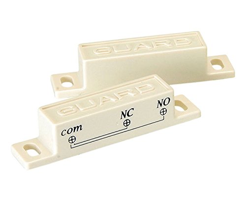
Does the locker door, reliably open/close when you need to switch on/off. A more robust and simpler solution would be to use a reed relay, which needs no power or circuitry at all. It just needs a suitably rated reed relay, in the door and a magnet, on the other side of the door (difficult to explain in words).
I.e. like they use in some burglar alarm window/door sensor switches.

Image for illustration ONLY. You need the correct, probably normally open type (or is it normally closed, I'm NOT sure in this application, which way round it goes, sorry), and suitable current rating parts. One end goes on the door, the other on the "wall" part of the locker. Potentially eliminating the entire rest of the circuitry.
You want closed when the units are separated and open when they are close together. I can't remember or don't know which way round they normally are.
« Last Edit: August 04, 2017, 01:46:46 pm by MK14 »
 
The following users thanked this post: Ian.M

Offline Nusa

  • Super Contributor
  • ***
  • Posts: 2416
  • Country: us
Re: Powering relay with 555 timer
« Reply #12 on: August 04, 2017, 01:51:28 pm »
If the locker is metal, the magnet side of that doesn't even need fastening. It'll stick on it's own. If it's too weak to not slide, you can replace it with a more powerful generic magnet.

Another option if you're using an arduino is to have it sense when the door is open with a photo-sensor (assuming lockers are dark and hallways aren't). Arduinos have some very low power modes if you program them right....battery consumption in the "off but checking an input often enough" state wouldn't be an issue.
« Last Edit: August 04, 2017, 01:56:04 pm by Nusa »
 
The following users thanked this post: Ian.M, MK14


Share me

Digg  Facebook  SlashDot  Delicious  Technorati  Twitter  Google  Yahoo
Smf