Hi everyone,
I am trying to trace PWM waveform from an Inverter that drives a 3 phase Induction Motor using an oscilloscope. The PWM waveform had been obtained but I am not sure if the method used is correct.
Here are specs of equipments used :
Motor : 3 phase, 0.75kW Induction Motor (MarelliMotori, MAA 80 MB 40)
Inverter : Emerson SKA 1200075
Oscilloscope : Agilent DSO 3062 (2-channel)
Differential Probe : Picotech TA 041 active differential oscilloscope probes
My goal :
To obtain the PWM waveform on oscilloscope and subsequently convert the signal to frequency domain using the FFT function on the oscilloscope. I am trying to correlate the noise and vibration of the motor with harmonics content in the PWM.
Here is what I have done:
1. Connect the differential probe lead to the motor terminals. In this case, they are connected to terminal U and W. (Phase-to-Phase)
2. The BNC end of the differential probe was connected to the oscilloscope’s Channel 1.
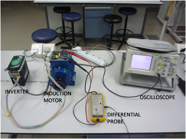 setup2
 by
vigren_6, on Flickr[/img]
Experimental Setup
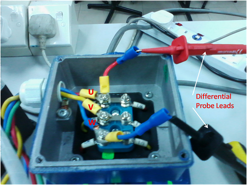 uvw2
uvw2 by
vigren_6, on Flickr[/img]
Probe leads connected to motor terminals
3. Display screen was split into two : Top- PWM waveform & Bottom-FFT result.
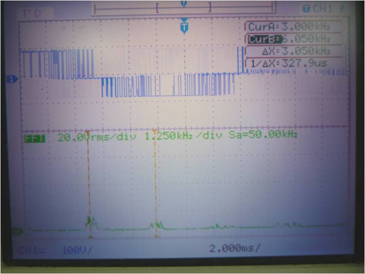 PWM3
PWM3 by
vigren_6, on Flickr[/img]
Screenshots of oscilloscope display
4. The motor was run to 1000 rpm and the result is shown below. The result indicates that the waveform is not a PWM but instead a SPWM (Sinusoidal PWM). Pulse width which starts thin becomes wide in the middle before returning back to thin in the end.
5. FFT has indicated harmonics of 3, 6 and 9 kHz was obtained. Cursor A – 3 kHz and Cursor B – 6 kHz.
My question is :
a. Is this the correct method to trace SPWM going into the motor? (phase-to-phase)
b. Or should it be referenced to ground?
c. Can the measurement be done without using the differential probe? By using 2 channels of the oscilloscope & measure phase-to-phase?
Thank you.


