Author Topic: Transistor selection confusion  (Read 2893 times)

0 Members and 1 Guest are viewing this topic.

Offline phaseformTopic starter

  • Regular Contributor
  • *
  • Posts: 82
  • Country: au
Transistor selection confusion
« on: May 16, 2018, 10:45:52 am »
I'm using a current sensing board from ebay to trigger an SSR, although the 'digital' output from the sensor board isn't ideal for the SSR.
I'm getting 0.2v low, and 2.2v high from the sensor board (with settings best I can figure to achieve), I want to use a transistor as a switch to send the full 5v through the SSR (3v min). The SSR draws ~5ma.
I have a BC639 (datasheet) I've found, which seems like overkill (1A max). Just from looking at transistor equations to figure out a base resistor, and whether this transistor is suitable.. I've gotten a bit confused. I'll have another look at it tomorrow, and probably get a lower power transistor from Jaycar.. Anyone with actual electronics knowledge that can shed some light on this..? - I was confused with min Hfe values - wont the base current just be lower in this case with a very low collector current?
 

Offline Benta

  • Super Contributor
  • ***
  • Posts: 5869
  • Country: de
Re: Transistor selection confusion
« Reply #1 on: May 16, 2018, 11:49:46 am »
For switching purposes, it does not help looking at the hFE figures, they are for linear operation. For a transistor of this size a good value for base current is IC / 25. Anything between 20 and 40 will also work.
 

Offline Audioguru

  • Super Contributor
  • ***
  • Posts: 1507
  • Country: ca
Re: Transistor selection confusion
« Reply #2 on: May 16, 2018, 01:01:54 pm »
Why add a high current transistor?
The current sensing board has a "TTL" output high which can drive the SSR without using an additional transistor and base resistor. With the (+) input of the SSR connected to +5V then the (-) input goes to 0.2V when the current sensor is triggered and has an input of 4.8V which is plenty.
 

Offline phaseformTopic starter

  • Regular Contributor
  • *
  • Posts: 82
  • Country: au
Re: Transistor selection confusion
« Reply #3 on: May 17, 2018, 04:27:43 am »
I can change the sensitivity of the sensor to get these outputs:
  • 5.2v trigger off, 2.75v trigger on
  • 0.15v trigger off, 2.7v trigger on
So it seems I can't use these values alone to drive the SSR.
I'm thinking a low power NPN transistor with the latter sensor settings.

I'm not sure about application of IC/25.. but I've done some reading around and maybe I've got it right....

I found this page on transistor calculation... so using for example a BC546 NPN Transistor..

From the datasheet which has "Figure 2. “Saturation” and “On” Voltages" - not sure why different datasheets dont show this info, nor how the Ic/Ib = 10 is found in this case
Ic = 5mA. Hence VBE = .75V
VBE = .75V is perfect for the sensor output values, with 2.7V sensor output (with 2kW through the sensor), I get ~1.95 voltage drop across the base resistor, at .5mA = 0.0005A (IC/10).
V=IR therefore R = 3900 Ohms

I think this is correct..
« Last Edit: May 17, 2018, 06:29:26 am by phaseform »
 

Offline Benta

  • Super Contributor
  • ***
  • Posts: 5869
  • Country: de
Re: Transistor selection confusion
« Reply #4 on: May 17, 2018, 08:54:15 am »
"not sure why different datasheets dont show this info, nor how the Ic/Ib = 10 is found"

Base current is set so high to make certain the transistor is driven 100% into saturation. Like I wrote, a ratio of 25 is normally enough.


Offline phaseformTopic starter

  • Regular Contributor
  • *
  • Posts: 82
  • Country: au
Re: Transistor selection confusion
« Reply #5 on: May 17, 2018, 10:29:57 am »
Nope, not saturated with 3k9
looking at Fig 2, maybe should design for 'worst case' Ic = 10mA. Hence VBE = .8V (datasheet)
2.7V sensor output, I get ~1.9 voltage drop across the base resistor, at 1mA (IC/10) = 0.001A.
V=IR therefore R = 1900 \$\Omega\$.
2V sensor output, 1.2V drop across the resistor, at 1mA = 0.001A
R = 1200 Ohms

So much for 3900..
hmm

With a 1200 Ohm part and say I only had 6mA for the SSR, therefore ~.75VBESAT => resistor voltage drop up to 1.95V possibly down to 1.25V if the sensor outputs only 2V
Ib=V/R = 1.25/1200 = 1.04mA
Ib=V/R = 2/1200 = 1.66mA

need to sleep on this..
answered. love.gif
Power=IV = Ib*VBE + IC*VCE =  0.00166*.8 + 0.01*0.6 = 0.007328W = 7.3mW = No problem...
« Last Edit: May 18, 2018, 03:00:33 am by phaseform »
 

Offline phaseformTopic starter

  • Regular Contributor
  • *
  • Posts: 82
  • Country: au
Re: Transistor selection confusion
« Reply #6 on: May 18, 2018, 04:43:02 am »
Not sure what I'm doing wrong here, but I'm getting 2.5VCE across my transistor, which should have less than 1V in saturation according to the datasheet.. which is defeating the point in the transistor :|

Getting resistor voltage drop of 2.36-.61 = 1.75 with 470 Ohm resistor, therefore IB = 1.75/470 = 0.003723 = 3mA, which seems like a lot for base current

whyyyyy  :scared:
« Last Edit: May 18, 2018, 04:47:31 am by phaseform »
 

Offline bson

  • Supporter
  • ****
  • Posts: 2269
  • Country: us
Re: Transistor selection confusion
« Reply #7 on: May 19, 2018, 03:38:55 am »
You're going about this the wrong way...  The current needs to be set by an emitter resistor, not a base resistor:


You have a 2.5V signal on the base.  You want 6mA current through RL:

RE = (2.5-0.7)/6m = 300

The resistance looking into the base is HFE * RE = approx 50k ohm ballpark

As the last step, add a base resistor to reduce the capacitive loading on the source, which are the green Ib switching currents in the plot below.


Note that with RL=100 Vce will be whatever it needs to be to produce the desired Ie, which given the fairly high base-facing resistance, is effectively Ic.  If you can't get the desired current this means you can't get sufficient voltage across RL; effectively Vcesat is too large and there's not enough headroom.  The 2.5V base current is plenty to drive a small BJT into saturation (if needed, to produce the desired current).

Vre = 6m*300 = 1.8V
Add Vcesat (0.2V?) and you have 2V
This means with a 12V supply you max out at 10V across RL
For a current of 6mA its resistance can't be more than 10/6m = ~1.6k
 
The following users thanked this post: phaseform

Offline phaseformTopic starter

  • Regular Contributor
  • *
  • Posts: 82
  • Country: au
Re: Transistor selection confusion
« Reply #8 on: May 20, 2018, 08:16:44 am »
Thanks for the info on this! this info was a little tricky to find!
RE = (2.5-0.7)/6m = 300
Not familiar with this equation? so VE = voltage across R2/IC?

Looking at the datasheet supplied by jaycar Vcesat should be below 1 V.

how is R1 not mentioned in transistor base resistor calculations generally?
« Last Edit: May 20, 2018, 08:40:51 am by phaseform »
 

Online Zero999

  • Super Contributor
  • ***
  • Posts: 19494
  • Country: gb
  • 0999
Re: Transistor selection confusion
« Reply #9 on: May 20, 2018, 09:11:11 am »
Thanks for the info on this! this info was a little tricky to find!
RE = (2.5-0.7)/6m = 300
Not familiar with this equation? so VE = voltage across R2/IC?

Looking at the datasheet supplied by jaycar Vcesat should be below 1 V.

how is R1 not mentioned in transistor base resistor calculations generally?
bson posted a different solution: drive the SSR off a constant current source. He assumed that the voltage from the drive and the voltage on the base is 2.5V, the transistor has a base-emitter voltage of 0.7V, therefore the voltage on the emitter will be 2.5-0/7 = 1.8V. The emitter resistor (R1) can then be chosen for the desired collector current: 6mA in this case I = V/R = 1.8/0.006 = 300R.

The trouble with this is I think the output voltage from the driver will be more than 2.5V, which was the voltage when loaded. The transistor will never saturate with this circuit. I'm not sure if this is what you want.


Offline bson

  • Supporter
  • ****
  • Posts: 2269
  • Country: us
Re: Transistor selection confusion
« Reply #10 on: May 21, 2018, 02:04:42 am »
RE = (2.5-0.7)/6m = 300
Not familiar with this equation? so VE = voltage across R2/IC?
...
how is R1 not mentioned in transistor base resistor calculations generally?
Vbe is a well-controlled property in that while it varies it doesn't vary much.  0.65 or 0.7V is a pretty reasonable value for BJTs (it goes up a little with current, maybe 0.05V or 0.10V).  It's a hallmark of BJTs.  If the voltage on the base is Vb, then the emitter voltage is Ve=Vb-Vbe; loop analysis (Kirchoff's voltage law) tells us this.  (One of the school exercises I still recall from the early 80s is loop analysis around BJTs.  Lots of them.)  Ohm's law tells us Ve = R1 * Ie, or R1 = Ve/Ie.  With a large base resistance (R1*Hfe) we know the base current Ib doesn't contribute much and Ie = Ic, to within 1/Hfe.  For an Hfe of 200 that means within 0.5%.  If Hfe varies from say 100-200 between individual units of a particular BJT, then this discrepancy between collector and emitter currents will vary between 0.5% and 1%.  Ic and Ie are pretty close, certainly no worse than the tolerances of a jellybean resistor.  So, R1 = (Vb - Vbe)/Ic to within ~1% or less.  It's also worth noting that a higher Hfe results in a small Vbe change, since they have the same root cause.

R1 is very much discussed in BJT loop analysis.  It's an essential part of it...  A lot of online material however tends to be rather incomplete, and you can't really provide a formula to plug numbers into for every situation.

Looking at the datasheet supplied by jaycar Vcesat should be below 1 V.

For small currents Vcesat doesn't matter, as long as you get the desired current.  In fact, an SSR, being a semiconductor device (typically a LED), switches on at a threshold voltage and is current driven.  Hence you need to drive it with a current, and Vce will be whatever it needs to be (pretty high) to set the input side (LED) current.  Too much current and input LED is gonski (as Dave would put it).
« Last Edit: May 21, 2018, 02:07:05 am by bson »
 

Offline phaseformTopic starter

  • Regular Contributor
  • *
  • Posts: 82
  • Country: au
Re: Transistor selection confusion
« Reply #11 on: May 23, 2018, 02:45:07 am »
I've created a schematic for this circuit, not sure if a BC639 will be suitable, don't fully understand driving for constant current, so I'm still unsure of what I'm trying to solve here. I don't really have much room for VCE for the SSR to operate fully.


Attaching a 10 Ohm resistor in series with the SSR connected to 5V source (wired as: 5v - SSR - resistor - 0V), I get approx .097 V, hence IC = .97/10 =~ 10 mA

The outcome I'm looking for is VCE < 1 V @ 10mA, in order to have max voltage across the SSR.

Open D0 is between 1.5-2.7 V depending on sensor current.. so Ideally, I'd like IC = 10 mA for D0 between 1.5-2.7 V...

But I'm confused as for crunching the numbers / transistor suitability. - I'm not sure the constant current circuit would leave enough voltage across the SSR
« Last Edit: May 23, 2018, 02:52:34 am by phaseform »
 

Offline bson

  • Supporter
  • ****
  • Posts: 2269
  • Country: us
Re: Transistor selection confusion
« Reply #12 on: May 23, 2018, 04:53:02 am »
R1 = (1.5-0.7V)/10mA = 80ohm

Why a BC639?  That's branded as a "High Current NPN Bipolar Transistor".  10mA is not "high current".  It's tiny small-signal stuff.   The jellybean of jellybeans BC548 (or 546, or 547 - they just differ in voltage tolerance, and are all perfectly fine) would be a better choice.  The BC548 has a Vcesat of 90mV typ and 250mV max @ 10mA, with a max Ic of 100mA.
 

Online Zero999

  • Super Contributor
  • ***
  • Posts: 19494
  • Country: gb
  • 0999
Re: Transistor selection confusion
« Reply #13 on: May 23, 2018, 08:41:06 am »
I'm using a current sensing board from ebay to trigger an SSR, although the 'digital' output from the sensor board isn't ideal for the SSR.
I'm getting 0.2v low, and 2.2v high from the sensor board (with settings best I can figure to achieve), I want to use a transistor as a switch to send the full 5v through the SSR (3v min). The SSR draws ~5ma.
I have a BC639 (datasheet) I've found, which seems like overkill (1A max). Just from looking at transistor equations to figure out a base resistor, and whether this transistor is suitable.. I've gotten a bit confused. I'll have another look at it tomorrow, and probably get a lower power transistor from Jaycar.. Anyone with actual electronics knowledge that can shed some light on this..? - I was confused with min Hfe values - wont the base current just be lower in this case with a very low collector current?
Something isn't right.

Is that 0.2V low and 2.2V high from the sensor board, with the SSR connected to its output?

The sensor board has an MCP6041 op-amp on it, which is being used as a comparator to generate the digital output. It has a rail-to-rail output, this means with no load, the output voltage swing equals the supply voltage. In this case it has an LED and 1k resistor (these are on the board) connected to the output, which will drop the voltage a little but not much. With a 5V supply, it should give 0V low and a little below 5V high, say 4.8V, when measured  with a meter.
http://www.dexsilicium.com/Microchip_MCP6041.pdf

All you need is this circuit.

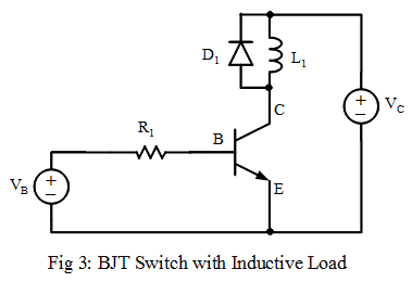
http://electronics-course.com/image/bjt-switch-inductor-load.png

In this case a solid state relay is not inductive, so the diode is not needed.

Suppose the output voltage from the sensor is 4.8V and the solid state relay draws 10mA.

Set the base current to 1/10 of the collector current, which is 1mA.

Calculate R1.

R = (V - VBE)/I

I = 1mA = 0.001A
V = 4.8V
VBE = 0.6V

R = (4.8-0.6)/0.001 = 4200Ω

In reality, the resistor is not critical: 3k3, 3k9 or 4k7 will do.

To answer the original question: the BC639 is overkill but will work. The BC548 is more than adequate, but if you only have the BC639, then it's fine.
« Last Edit: May 23, 2018, 08:43:03 am by Hero999 »
 

Offline phaseformTopic starter

  • Regular Contributor
  • *
  • Posts: 82
  • Country: au
Re: Transistor selection confusion
« Reply #14 on: May 23, 2018, 09:06:13 am »
so yes, I am using a BC546, BC639 is one I had already and decided it was not ideal, so I got some BC546 parts.. D0 is giving 0.3 V low, and at least 1.5 V high (up to 2.7 V no load), D0 varies with sensor current, and isn't really a digital signal in my config at least. I played around with the adjustment pot and that's the best I could get, don't fully understand how the tuning worked. I went and got one of these arduino compatible relay boards because I wanted the SSR switching to be discrete (on/off), it draws 150mV through the sense pin over a 10 Ohm resistor = 15mA (wired as: 5v -  resistor - relay board sense pin).
So next is to figure BC546 (derp) resistor values to trigger this relay board for >= 1.5 V D0 output... it will have to wait for now. So much for a simple project... as with every case.
 

Online Zero999

  • Super Contributor
  • ***
  • Posts: 19494
  • Country: gb
  • 0999
Re: Transistor selection confusion
« Reply #15 on: May 23, 2018, 09:59:55 am »
so yes, I am using a BC546, BC639 is one I had already and decided it was not ideal, so I got some BC546 parts.. D0 is giving 0.3 V low, and at least 1.5 V high (up to 2.7 V no load), D0 varies with sensor current, and isn't really a digital signal in my config at least. I played around with the adjustment pot and that's the best I could get, don't fully understand how the tuning worked. I went and got one of these arduino compatible relay boards because I wanted the SSR switching to be discrete (on/off), it draws 150mV through the sense pin over a 10 Ohm resistor = 15mA (wired as: 5v -  resistor - relay board sense pin).
So next is to figure BC546 (derp) resistor values to trigger this relay board for >= 1.5 V D0 output... it will have to wait for now. So much for a simple project... as with every case.
Something is wrong with the current sensor board or power supply. The digital output should be more than 2.7V, unloaded and it should be independent of the potentiometer setting.

Have you checked the sensor board is actually getting 5V?
Are you sure you're not measuring the analogue output?

The circuit I posted previously will work fine at lower input voltages. It will probably still work with 3k3 to 4k7 and an input voltage of 2.7V, since the Hfe of the transistor will be well in excess of 10. If the SSR still doesn't activate with it, then reduce R1 to 2k2 or 1k8.
 

Offline phaseformTopic starter

  • Regular Contributor
  • *
  • Posts: 82
  • Country: au
Re: Transistor selection confusion
« Reply #16 on: May 26, 2018, 07:03:31 am »
I think the sensor board is causing all the issues here...
If I run the digital sensor output to the input of the arduino relay board, I get the relay switching on/off at what i guess is line frequency. Even if I only put 2.6v DC into the relay (5v through a resistor), it will trigger, with a dimly lit indicator LED, that same voltage from the sensor output will cause the relay to switch on/off like crazy. I tried some random electrolytic caps to smooth this to no avail - haven't tried finding a correct filter cap as a potential solution..

re the sensor board: Around the middle of the adjustment pot, I get:

no current: 5.2v light off
high current: 2.9v light on

other setting:
no current: 0.3v light on
high current: 2.7v light dim

those values are around the middle of the trimpot, and have the greatest change in voltage. The analog output was just noisy to my DMM
« Last Edit: May 26, 2018, 07:07:20 am by phaseform »
 

Offline Doctorandus_P

  • Super Contributor
  • ***
  • Posts: 3342
  • Country: nl
Re: Transistor selection confusion
« Reply #17 on: May 26, 2018, 01:00:38 pm »
You're going to a shop to buy a single transistor?
Sounds weird, unless it's some special transistor.

I can highly recommend a "transistor assortment kit" from Ali / Ebay / China / Whatever.
300 or 600 transistors ifn different sizes and polarities.
Always fun to experiment with, and no harm done if you let some of the magic smoke out.

Your first job would be to get the datasheets of the transistors involved.
Then make some comparisons, and select a nice kit on the bases of the selction in the kit.
There are quite some differences between those kits.
 

Offline phaseformTopic starter

  • Regular Contributor
  • *
  • Posts: 82
  • Country: au
Re: Transistor selection confusion
« Reply #18 on: May 27, 2018, 08:14:06 am »
nice, I'm just going pragmatic
 :-//
rather than get too far into dealing with whatever this sensor is handing out, without buying a scope


Share me

Digg  Facebook  SlashDot  Delicious  Technorati  Twitter  Google  Yahoo
Smf