That's the storage time. You'll only notice a difference, if the transistor is driven into saturation. If the series current limiting to the base is high enough, then the transistor will not go into saturation and will turn off quickly, even with the diode.
Yes, storage time is a huge part of it, in saturated mode. The collector can sit there drifting for
tens of microseconds, even though the base terminal current is absolutely zero!
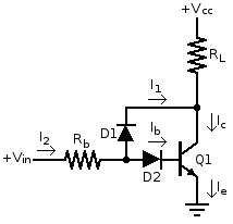
Another way to ensure it doesn't saturate is to with a Baker clamp. Add a diode with its cathode connected to the collector and the anode connected to the anode of the diode in series with the base. When the transistor starts to saturate, current is diverted away from the base, via the collector to the emitter, bypassing it.
This helps, but helps the most as a combination approach.
Just now I set up a circuit which I expect will meet your approval: the schematic as shown above, with 1k base resistor, 0/5V square wave input, a pair of 1N914, a 2N3904, and a 220 ohm collector load (to a +12V supply).
The waveform: well darn, my camera battery is low, so I'll have to describe it. Anyway,
On the input falling edge, collector voltage does begin to rise immediately (the Baker clamp is indeed doing its job). Starting from "saturation" (about 0.8V), for the first 270ns, it rises approximately linearly, to 4V. Then the decay is approximately exponential, with a time constant of about 300ns. The 10-90% rise is 680ns.
In the same time frame, base voltage barely falls at all, starting around 800mV and only falling to 600mV after a whopping 2.5us. Given the Ebers-Moll equation says 60mV/decade, that means the collector current has only decreased by 2000x in that time, or reaching 25uA. While that's quite a bit more "off" than it started, it still has a seriously long way to go before being truly cut off (~nA!).
Whereas if I simply add a B-E resistor of 1k, the input-falling propagation delay is 110ns, collector rise time is 85ns and base storage time is 160ns.
Still not convinced it's voltage not current? Come on, you people are hopeless...

Tim


