Hello,
I'm feeding a 5V PWM signal (500Hz) into the base of an ULN2003A Darlington Transistor Array (Datasheet:
http://www.ti.com/lit/ds/symlink/uln2003a.pdf) and using it to sink a 10V rail to ground. The problem is that when I scope the output, the amplified PWM signal looks incorrect. Also, changing the probe attenuation from 10x to 1x significantly changes the characteristic of the transient element of interest (for the better).
1. The rail is not being overloaded. Its output is regulated 10V and looks stable. All measurements taken with "open" outputs, probing the terminals of interest directly.
2. The PWM input is accurate and the GND is common across +5V and +10V rails.
The circuit diagram:

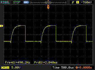
Behavior observed at 1x scope attenuation:
Behavior observed at 10x scope attenuation:

Different duty cycle at 10x scope attenuation:

What I want is a clean square wave. What looks to be happening now is a clean transition when the darlington switches ground on, but then a really lazy/capacitive rise time to +10V from ground when the darlington switches off.
Is this the expected behavior? Any thoughts? Thanks.
Geekbot2k


