Author Topic: Would you help me understand this simple circuit 555?  (Read 3051 times)

0 Members and 1 Guest are viewing this topic.

Offline Michael GeorgeTopic starter

  • Contributor
  • Posts: 22
  • Country: eg
Would you help me understand this simple circuit 555?
« on: June 18, 2016, 11:53:16 pm »
I would like to use 555 as monostable to make a timer of 1 hour. I used very high values of capacitors and resistors such as: 20 Mohm and 1000 uF.
The output of 555 was always HIGH and it is not able to be LOW.
I googled and I found that there is a leakage current of capacitor and I have some questions:

1. Is this leakage current due to the nature of electrolytic capacitors? Or the capacitor discharge through the 555? In other words, What causes leakage? The capacitor itself or the 555?

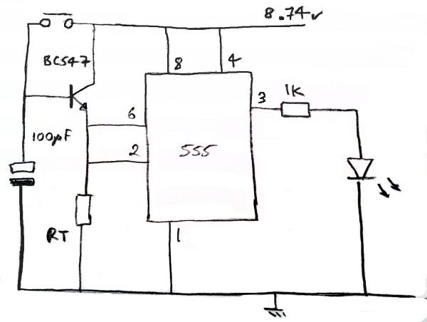
I also found the solution of this issue, The following circuit was very helpful. It allows me to make a timer of 1.5 hours or even more.

2. Would you tell me how this circuit works? I know how monostable operation work but I don't understand the function of the transistor and how can it prevent the leakage current and how the capacitor is charged and discharged.


3. If the leakage current is due to 555 , Can I exploit it and use a capacitor only without the transistor and the resistor?
One terminal of the capacitor would be connected to the ground and the other terminal would be connected to both pins 2 and 6.
The capacitor would be discharged through the 555 because it takes the leakage current from the capacitor. It would be charged again by a bush button.

Thank you very much,
 

Offline uncle_bob

  • Supporter
  • ****
  • Posts: 2441
  • Country: us
Re: Would you help me understand this simple circuit 555?
« Reply #1 on: June 19, 2016, 12:34:03 am »
Hi

Any circuit you try to build with an R/C time constant beyond about 100 seconds will either be very flakey or not work at all. Capacitors all have leakage. Your circuit board has leakage. Anything you attach to your R/C will have leakage.

The second circuit you show does not appear to do what you think it does. Either there is an error in the schematic or in the description.

Bob
 
The following users thanked this post: Michael George

Offline Signal32

  • Frequent Contributor
  • **
  • Posts: 251
  • Country: us
Re: Would you help me understand this simple circuit 555?
« Reply #2 on: June 19, 2016, 12:40:56 am »
Any circuit based on 555 won't be accurate with timings beyond a few seconds. Even 5 seconds is pushing it. If you build a 555 circuit with a 10 second delay it's very likely that the next one you build will have 9s and the next one 11s ( due to variance in the components ).

Now, to answer your questions:
1. Is this leakage current due to the nature of electrolytic capacitors? Or the capacitor discharge through the 555? In other words, What causes leakage? The capacitor itself or the 555?
Probably the biggest leakage in your scenario is through the 555, after all it does have to draw some power in order to "read" the voltage level of the capacitor. After that, the capacitor leakage would be 2nd.


2. Would you tell me how this circuit works?
That circuit still doesn't work for your scenario. What do you need the circuit for ?

3. If the leakage current is due to 555 , Can I exploit it and use a capacitor only without the transistor and the resistor?
The leakage current can vary a lot from chip to chip(10x+? if using 555's from diff manufacturers), so that's not a correct way to design a circuit.

If you must use a 555, you can feed it's output to a CD4060, and divide it by say 2^14 = 16384, so your 555 has to oscilate at ~5Hz to get a 1 hour delay, much more obtainable.
Note that you could just use a CD4060 on it's own as it has a built-in oscilator -- http://www.electronicecircuits.com/electronic-circuits/cd4060-timer-circuit-1-minute-to-2-hours
« Last Edit: June 19, 2016, 12:53:00 am by Signal32 »
 
The following users thanked this post: Michael George

Offline SeanB

  • Super Contributor
  • ***
  • Posts: 16276
  • Country: za
Re: Would you help me understand this simple circuit 555?
« Reply #3 on: June 19, 2016, 09:05:50 am »
The perfect IC for long delay was the ZN1034E.

http://www.datasheetarchive.com/dlmain/Databooks-5/Document204166.pdf

About the same power consumption of the 555, but the time could be up to 12 hours with good repeatability, and it included a built in voltage regulator.
 
The following users thanked this post: Michael George

Offline Zero999

  • Super Contributor
  • ***
  • Posts: 19494
  • Country: gb
  • 0999
Re: Would you help me understand this simple circuit 555?
« Reply #4 on: June 19, 2016, 12:49:09 pm »
The ZN1034E is obsolete. A quick search revealed some expensive sales on ebay but they may be fake.

Use the CD4536, CD4541 or even the CD4060, which are still made and use less power than the 555.
 
The following users thanked this post: Michael George

Offline uncle_bob

  • Supporter
  • ****
  • Posts: 2441
  • Country: us
Re: Would you help me understand this simple circuit 555?
« Reply #5 on: June 19, 2016, 02:01:52 pm »
The ZN1034E is obsolete. A quick search revealed some expensive sales on ebay but they may be fake.

Use the CD4536, CD4541 or even the CD4060, which are still made and use less power than the 555.

Hi

Hate to say it, but these days, the low cost approach for a one hour timer .... use an MCU. No external parts, six or eight pins, not very big. Pick any of a dozen outfits to buy it from. Pick any of several dozen parts from any of them. Costs well under 50 cents for the chip. Program it up for however many years / months / weeks/ days / hours / minutes of delay you happen to want. Probably accurate to 1% off the shelf and can be calibrated to hold 0.1%. If you pick the right part, it pulls far less current than the 555. Think of all the money you will save on electric bills :)

Bob
 
The following users thanked this post: Michael George

Offline Zero999

  • Super Contributor
  • ***
  • Posts: 19494
  • Country: gb
  • 0999
Re: Would you help me understand this simple circuit 555?
« Reply #6 on: June 19, 2016, 09:02:54 pm »
Yes, I microcontroller is a good idea but I didn't want to suggest that, because I knew someone else would.

There are reasons though why an old CMOS IC may be preferable, such as not requiring a voltage regulator and the fact that it still is often cheaper. I've seen it before in commercial projects. I looked inside an electric blanket timer which had stopped working because the thermal fuse had gone and there was no MCU, just a MC14541. This wasn't a particularly old product. The date of manufacture was around 2010.

I've quickly looked on the RS Components site and the x4541 is still cheaper than the lowest cost MCU.
 
The following users thanked this post: Michael George


Share me

Digg  Facebook  SlashDot  Delicious  Technorati  Twitter  Google  Yahoo
Smf