Author Topic: How Direct Digital synthesis works  (Read 6773 times)

0 Members and 1 Guest are viewing this topic.

Offline Kedar264Topic starter

  • Regular Contributor
  • *
  • Posts: 117
  • Country: in
  • Listen to Your Voice
How Direct Digital synthesis works
« on: May 25, 2015, 05:50:36 pm »
Recently i posted my design of 30 mhz sine wave generator in project and design stuff, can you explain how dds works?

https://www.eevblog.com/forum/projects/30-mhz-ad9850-dds-signal-generator-in-12$/
 

Offline Dave

  • Super Contributor
  • ***
  • Posts: 1352
  • Country: si
  • I like to measure things.
Re: How Direct Digital synthesis works
« Reply #1 on: May 27, 2015, 01:35:37 am »
It's incredibly simple, actually.


You have a counter (phase accumulator) that adds a fixed number (frequency setting word) to its own value on every clock cycle. This counter has a certain number of bits, therefore an upper limit. When the sum exceeds this limit, it simply overflows.
Example:
Freq. setting word = 25
Number of bits = 7 (can hold values from 0 to 127)
0, 25, 50, 75, 100, 125, 23, 48, 73, 98, 123, 21,...
                                      ^Overflow                 ^Overflow

If you plotted these numbers onto a graph, it would look like a sawtooth wave. The inclination of the slope will depend on the FSW you select. The higher the number, the faster the slope will climb.

You then have a sine loop-up table. It describes a single sine wave (0-360°) with 2^N points. Here is an example for a 4-bit (16 values) sine look-up:
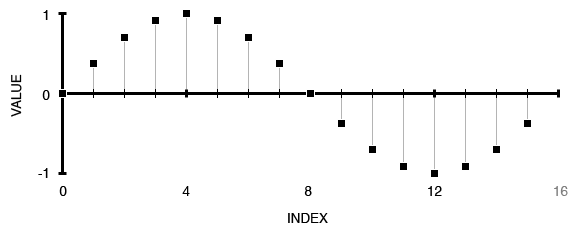

The upper bits of your phase accumulator are fed into the look-up table. You are feeding in a sawtooth, so that means it is repetitively scanning through the values of a sine wave. If your FSW is low, it is going to scan through slowly, if it is very high, it is only going to throw out a couple of points of every sine. The number of overflows per second equal your output sine frequency.

The value you get out of this LUT is then fed into a DAC that translates these numbers into analog voltages.

The problem here is that you have sharp transitions between these analog voltage steps, which means you have a lot of higher harmonic content, which you do not want. This is solved with a low-pass filter, that cleans out the higher harmonics, leaving you with a nice smooth sine wave.

I have way too much time on my hands, so I have made a simple excel demonstration. Try tweaking the FSW and observe the output waveform. ;D
« Last Edit: June 16, 2015, 02:33:44 am by Dave »
<fellbuendel> it's arduino, you're not supposed to know anything about what you're doing
<fellbuendel> if you knew, you wouldn't be using it
 

Offline hamster_nz

  • Super Contributor
  • ***
  • Posts: 2803
  • Country: nz
Re: How Direct Digital synthesis works
« Reply #2 on: May 27, 2015, 02:51:33 am »
Oh, and if you want to you can interpolate between samples in the lookup table using some of the unused bits from the phase accumulator to increase the resolution (in samples per cycle) of the table.

This doesn't upset things, as when a sine wave is sampled with enough points per cycle the segments between samples are very close to being straight lines.

e.g.

If there is a 36 entry table (which you wouldn't actually use because it isn't a power of 2, but it makes the numbers easy....), each sample is 10 degrees apart:

sin(40 degrees) = 0.64278761
sin(50 degrees) = 0.766044443

Interpolated mid-point (at 45  degrees) 0.704416026

Actual value of sin(45) is 0.707106781 giving an error 0.38%, which I think is the worst case.

You don't really need a big table, esp considering that you can exploit the symmetry of a sine to get rid of 3/4s of the entries...


Gaze not into the abyss, lest you become recognized as an abyss domain expert, and they expect you keep gazing into the damn thing.
 

Offline Skimask

  • Super Contributor
  • ***
  • Posts: 1433
  • Country: us
Re: How Direct Digital synthesis works
« Reply #3 on: May 27, 2015, 03:47:29 am »
If there is a 36 entry table (which you wouldn't actually use because it isn't a power of 2, but it makes the numbers easy....), each sample is 10 degrees apart:

sin(40 degrees) = 0.64278761
sin(50 degrees) = 0.766044443

Interpolated mid-point (at 45  degrees) 0.704416026

Actual value of sin(45) is 0.707106781 giving an error 0.38%, which I think is the worst case.
Wouldn't the worst case be between 0 and 10, where the "slope" is steepest?
I didn't take it apart.
I turned it on.

The only stupid question is, well, most of them...

Save a fuse...Blow an electrician.
 

Offline hamster_nz

  • Super Contributor
  • ***
  • Posts: 2803
  • Country: nz
Re: How Direct Digital synthesis works
« Reply #4 on: May 27, 2015, 04:30:34 am »
Wouldn't the worst case be between 0 and 10, where the "slope" is steepest?

If we are talking about the error between the interpolated value and the actual value (which I was) then we're both wrong!

sin(0) = 0
sin(10) = 0.1736481419
Interpolated value = 0.086824071
actual value of sin(5) = 0.0871557247
error = 0.0003316537

The error is the highest just at the crest...

sin(80) 0.9848077026
sin(90) 1.0
Interpolated for value 0.9924038513   
actual value for sine(85) 0.9961946712
error = 0.0037908199

Strangely enough, if rather than using (a+b)/2 to interpolate, but (a+b)/2*1.0038198359, the error is reduced to so close to zero that it disappears.

That must be due to if you add two sine waves of the same frequency but a different phase you end up with a sine wave of the same frequency, but with a different phase and magnitude.

1.0038198359 must be some how related to 5 degrees.... oh it is 1/cos(5 degrees). Humm....

Gaze not into the abyss, lest you become recognized as an abyss domain expert, and they expect you keep gazing into the damn thing.
 

Offline Skimask

  • Super Contributor
  • ***
  • Posts: 1433
  • Country: us
Re: How Direct Digital synthesis works
« Reply #5 on: May 27, 2015, 05:01:36 am »
Then you get into that whole thing of taking pi out to 39 places gets you down to the accuracy of a hydrogen atom over the expanse of the visible universe...

Point being, a guy doesn't have to be as close with sin/cos/tan/etc as they think they do...and you just proved it out to about 3-4 decimal places.  2 ^-10 gets you 0.0009765625, 3 'leading' zeros there.  More than good enough for DDS applications.  10 bit lookup table (or 8 bits if a 1/4 wave table is used appropriately) is all a person really needs.
I didn't take it apart.
I turned it on.

The only stupid question is, well, most of them...

Save a fuse...Blow an electrician.
 

Offline German_EE

  • Super Contributor
  • ***
  • Posts: 2399
  • Country: de
Re: How Direct Digital synthesis works
« Reply #6 on: May 27, 2015, 02:12:44 pm »
A DDS chip with a 10-bit accumulator is available but it produces a very poor sine wave, especially for RF work. The minimum is generally considered to be something like the AD9851 which is 32 bit and can accept a clock up to 180 MHz, this gives a workable output up to 70 MHz but you still need to use a low pass filter on the output.

32 bit DDS chips are now available with 1 GHz clocks and beyond, the output from these devices is remarkably pure.
Should you find yourself in a chronically leaking boat, energy devoted to changing vessels is likely to be more productive than energy devoted to patching leaks.

Warren Buffett
 

Online tggzzz

  • Super Contributor
  • ***
  • Posts: 19508
  • Country: gb
  • Numbers, not adjectives
    • Having fun doing more, with less
Re: How Direct Digital synthesis works
« Reply #7 on: May 27, 2015, 02:57:27 pm »
To save repetition and off-the-cuff explanations, have a look at:
https://www.eevblog.com/forum/projects/30-mhz-ad9850-dds-signal-generator-in-12$/msg681206/#msg681206
https://www.eevblog.com/forum/projects/30-mhz-ad9850-dds-signal-generator-in-12$/msg681320/#msg681320
There are lies, damned lies, statistics - and ADC/DAC specs.
Glider pilot's aphorism: "there is no substitute for span". Retort: "There is a substitute: skill+imagination. But you can buy span".
Having fun doing more, with less
 

Offline kony

  • Regular Contributor
  • *
  • Posts: 242
  • Country: cz
Re: How Direct Digital synthesis works
« Reply #8 on: May 27, 2015, 03:04:14 pm »
But is there any decent, fully integrated DDS not costing leg and arm?
Acumulator resolution is not everything you need for decent SFDR.

I'm currently in design process of device requiring multiple DDS outputs and so far it seems my best bet is FPGA + 275Msps 14b DACs (output BW limited to 90MHz or thereabouts, SFDR >75dB needed).

Also saying that 10b adress spacce LUT is enough is quite bold claim - it heavily depends on particular use for the DDS, or better to be said required dynamic range. And LUT size does not have to be same as the phase accumulator resolution, actually they are quite different in most cases.

I don't see noise shaping / dithering mentioned in this thread. I'd strongly recommend reading http://www.xilinx.com/support/documentation/ip_documentation/dds.pdf for example. Analog devices has also plenty of documents covering this.
« Last Edit: May 27, 2015, 03:05:58 pm by kony »


Share me

Digg  Facebook  SlashDot  Delicious  Technorati  Twitter  Google  Yahoo
Smf