Author Topic: EEVblog #401 - Lecroy 9384C Oscilloscope Repair - Part 2  (Read 38389 times)

0 Members and 1 Guest are viewing this topic.

pir

  • Guest
Re: EEVblog #401 - Lecroy 9384C Oscilloscope Repair - Part 2
« Reply #25 on: December 21, 2012, 05:33:36 pm »
Hey Dave...
what do you measure on OFF and ON situation from the PS over that 2pin cable?
if it is -2V ~ -3V BINGO!!!

possible combinations inside that PS and output over that 2 pins:
12V-15V=-3V
5V-7V=-2V

THERE IS YOUR FLOATING GROUND  ;D
..and maybe that short is inside the PS
please measure the "3.3V pin2,pin3" over that 2pin plug for pass through...
please measure the "3.3V,pin1" over the "3.3Vpin2,pin3"
please measure the "3.3V pin2,pin3" to other pins of that plug (coupled with a feedback controlled -3.3V PS out)

p.s. i told my shelf to just take a look over a Leroy schematic for a minute and i am doing it all day...  ::)
..and going over the videos again i thought that this 2pin cable is way too fat to be a feedback to PS....
why there are 2 headers of this kind? what is the second one ?

<Edit>
the 9374 is different from 9384 in that 2pin header and the floating is done with some regulators.
the 9384 service manual from the link i posted , does not have the pages of the 3.3V and the diagrams are hard to read

"i want to see that old horse running again"
<Edit>


<Edit>
that 2pin header is actually a 3pin header , red-black-white
<Edit>

<Edit>
i see a -3.3V or what?
damn...totally unreadable
see pic
<Edit>
« Last Edit: December 21, 2012, 07:48:51 pm by pir »
 

Offline bpn1028

  • Newbie
  • Posts: 7
  • Country: us
Re: EEVblog #401 - Lecroy 9384C Oscilloscope Repair - Part 2
« Reply #26 on: December 21, 2012, 06:17:29 pm »
Is it possible that it is no longer shorted and the original short was vaporized by the current applied?   I don't recall seeing it tested again with the Ohm meter after all that current was applied for a long time.  I know it is drawing more current than expected, but is it really still shorted?
 

Offline cengland0

  • Contributor
  • Posts: 49
Re: EEVblog #401 - Lecroy 9384C Oscilloscope Repair - Part 2
« Reply #27 on: December 21, 2012, 06:58:37 pm »
Actually I think Dave was right. There are several factors to consider when using IR camera. First is of course the scaling of colors you mentioned.

Second is that FLIR doesn't measure temperature direcly but IR radiation that can be subject to phenomena any radiation is, namely: transmission and reflection, so measuring temp of shiny surfaces can be tricky (the same is when you are trying to take a photo of a mirror, you not only take photo of mirror itself but also of objects reflecting from its surface). And this happened there on BNC. Camera was showing effect of combined radiation from the BNC itself as well as radiation reflected from eg. Dave's hand.

Third factor is that different materials have different emmissivity coefficients (dependent on color, roughness, etc), so that when measuring its temp you should first set proper coefficient in the camera to make accurate measurements. Thats why, probably, absolute values measured in the video were somewhat off. But in this case it was all about relative temp not absolute.

What you're saying can happen; however, in the case of this troubleshooting video, I respectfully disagree with you.  If you look at the video at 31:05, you can clearly see that the scale is at 26.2 max and 22.2 min.  The Flir will automatically detect the hottest items within that range and colorize them accordingly.  The rest of the video toward the end it appears Dave figured out how to fix the scale to 89.5 max and 25.7 min and that's when you do not see the heat coming from those BNC connectors.

In the video, at 7:24 he tests the bench temperature and it's 24-25 degrees.  So you're only looking at a 1.2 degree difference from the bench to the maximum of the Flir scale.  The Flir is sensitive enough to pick up that temperature difference in the 22.2 to 26.2 range and show you that the BNC connectors are warmer.

For your homework today,  :), try this.  Heat up a shiny piece of metal to 100 degrees that is extremely reflective.  Then, using a temperature probe of that metal while it is angled toward a block of ice, what temperature would it read?  I remember the Mythbusters getting past an IR alarm sensor by using a piece of glass because the unit couldn't "see" behind that glass.  They used a similar visual IR heat detection device as well and it was completely the temp of the glass and not what was behind it.  So even though I haven't performed this test myself, I would guess the temp it would read is close to the 100 degree side instead of the 0 degree side.
 

Offline lewis

  • Frequent Contributor
  • **
  • Posts: 704
  • Country: gb
  • Nullius in verba
Re: EEVblog #401 - Lecroy 9384C Oscilloscope Repair - Part 2
« Reply #28 on: December 21, 2012, 08:18:51 pm »
Actually I think Dave was right. There are several factors to consider when using IR camera. First is of course the scaling of colors you mentioned.

Second is that FLIR doesn't measure temperature direcly but IR radiation that can be subject to phenomena any radiation is, namely: transmission and reflection, so measuring temp of shiny surfaces can be tricky (the same is when you are trying to take a photo of a mirror, you not only take photo of mirror itself but also of objects reflecting from its surface). And this happened there on BNC. Camera was showing effect of combined radiation from the BNC itself as well as radiation reflected from eg. Dave's hand.

Third factor is that different materials have different emmissivity coefficients (dependent on color, roughness, etc), so that when measuring its temp you should first set proper coefficient in the camera to make accurate measurements. Thats why, probably, absolute values measured in the video were somewhat off. But in this case it was all about relative temp not absolute.

What you're saying can happen; however, in the case of this troubleshooting video, I respectfully disagree with you.  If you look at the video at 31:05, you can clearly see that the scale is at 26.2 max and 22.2 min.  The Flir will automatically detect the hottest items within that range and colorize them accordingly.  The rest of the video toward the end it appears Dave figured out how to fix the scale to 89.5 max and 25.7 min and that's when you do not see the heat coming from those BNC connectors.

In the video, at 7:24 he tests the bench temperature and it's 24-25 degrees.  So you're only looking at a 1.2 degree difference from the bench to the maximum of the Flir scale.  The Flir is sensitive enough to pick up that temperature difference in the 22.2 to 26.2 range and show you that the BNC connectors are warmer.

For your homework today,  :), try this.  Heat up a shiny piece of metal to 100 degrees that is extremely reflective.  Then, using a temperature probe of that metal while it is angled toward a block of ice, what temperature would it read?  I remember the Mythbusters getting past an IR alarm sensor by using a piece of glass because the unit couldn't "see" behind that glass.  They used a similar visual IR heat detection device as well and it was completely the temp of the glass and not what was behind it.  So even though I haven't performed this test myself, I would guess the temp it would read is close to the 100 degree side instead of the 0 degree side.

I'm afraid gszo123 is bang on. IR emissivity and surface reflections are serious problems when trying to make accurate measurements with a thermal imaging camera. Those BNCs were not warm, it was reflected body heat.

Just for fun, I'd thought I'd try your experiment:

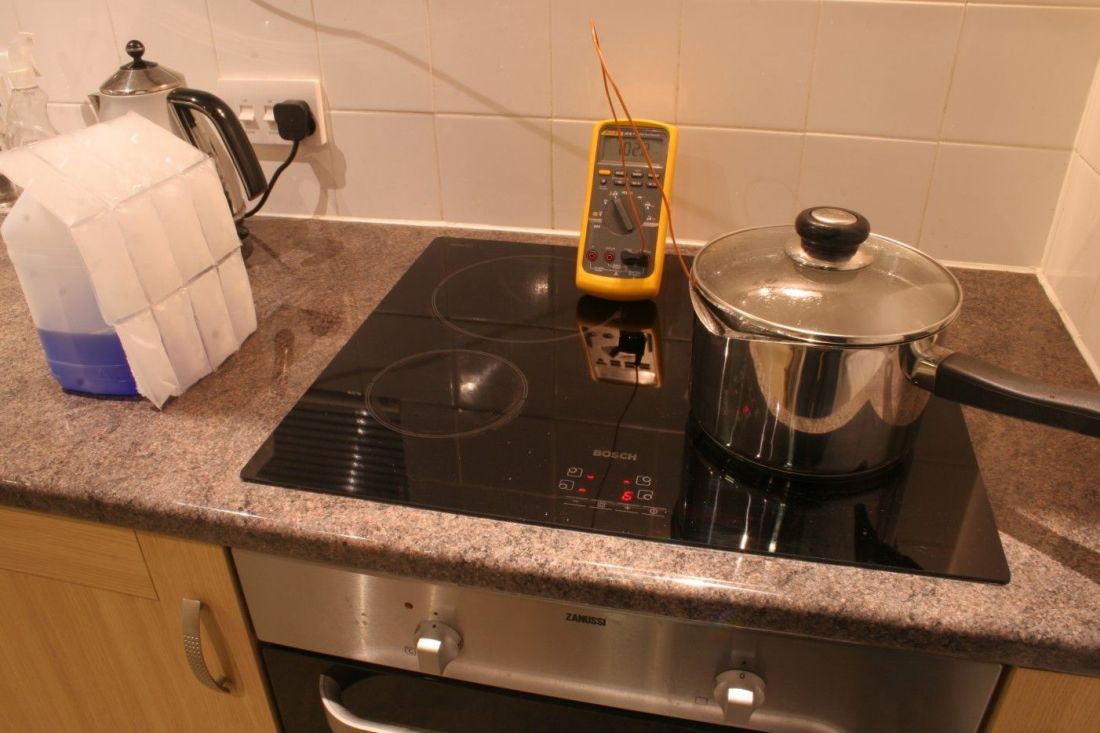
Here's the setup using a saucepan, boiling water, ice, a tub of CarPlan four seasons screenwash and a Fluke Ti10 thermal imaging camera. (Yes, ABELtronics Limited is winding down for Christmas). The highly polished stainless steel saucepan is boiling on my workshop hob. An ice pack rests against the screenwash tub facing the saucepan:
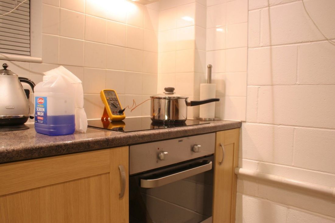


Different angle:


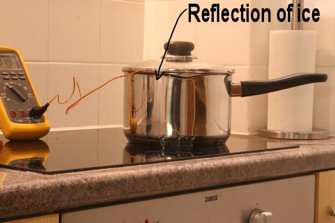
A closeup reveals you can see the reflection of the ice pack in the side of the saucepan:


The water in the saucepan is boiling:


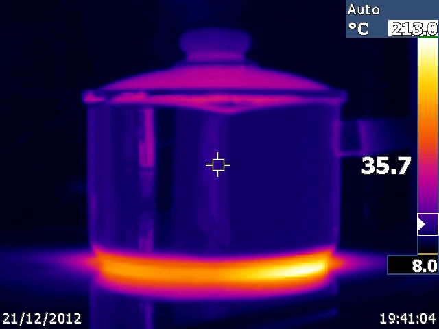
Here's a thermal image of the side of the saucepan. The temperature shown on the right (35.7C) is the temperature of the crosshair in the middle of the image. Note it's a lot colder than it should be (100C) because of the poor IR emissivity of the polished stainless. (The ghostly lighter blue bit right under the crosshair is a thermal reflection of me taking the image):


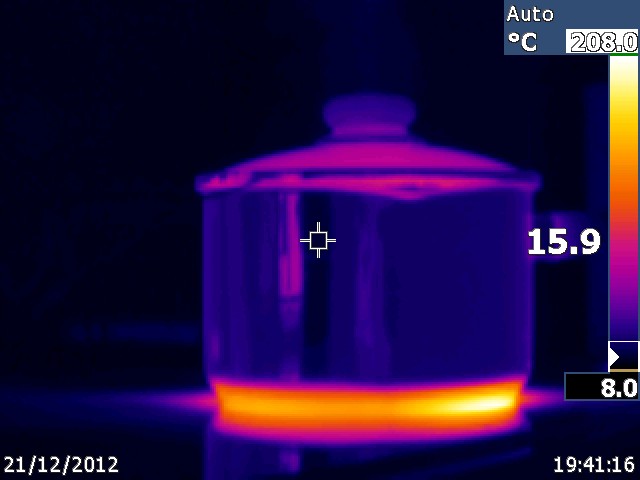
Moving the crosshair over the reflection of the ice shows the TI camera thinks the saucepan is apparently 15.9C at the point where the ice is reflecting. You can see the reflection of the kettle slightly to the left. Remember the saucepan is at 100C:


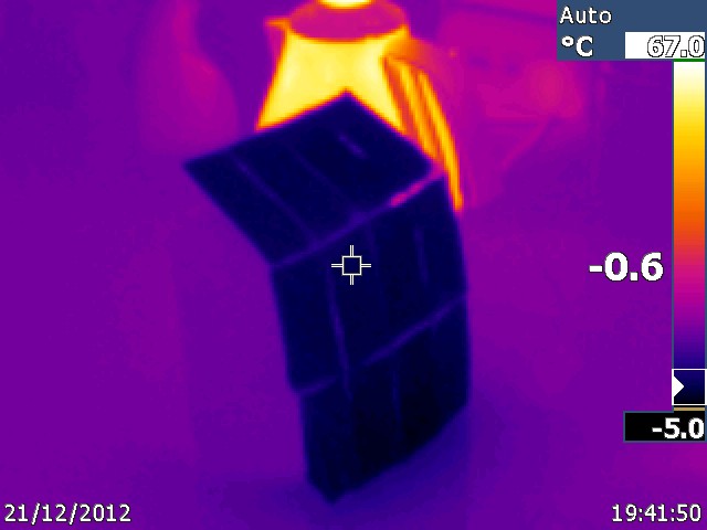
The ice pack is showing as -0.6C (the warm kettle can be seen in the background):


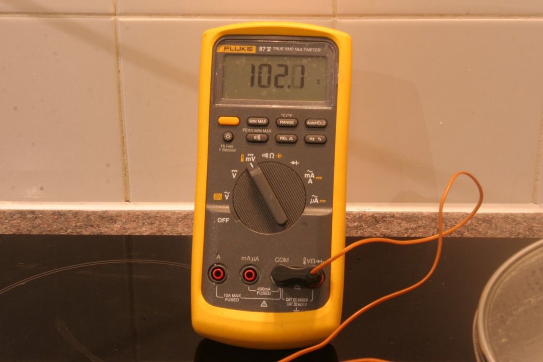
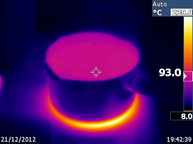
With the pan lid off the TI camera thinks the water is 93C, but the side of the saucepan is considerably colder:


So in answer to your comment, even with a polished bit of metal at 100C reflecting off ice, the TI camera still errs towards the colder end.

Thermal reflections are a problem and definitely are a trap for young players!


I will not be pushed, filed, stamped, indexed, briefed, debriefed or numbered.
 

Offline gazza666

  • Newbie
  • Posts: 5
Re: EEVblog #401 - Lecroy 9384C Oscilloscope Repair - Part 2
« Reply #29 on: December 21, 2012, 09:08:45 pm »
Dont Give up Dave
Great Stuff
 

Offline c_francof

  • Newbie
  • Posts: 2
Re: EEVblog #401 - Lecroy 9384C Oscilloscope Repair - Part 2
« Reply #30 on: December 21, 2012, 09:46:25 pm »
Isn't it better to use the external 11 Amp font and with the multimeter going testing different 3.3v rail points and detect where is the less Volt drop in the rail, I mean , with 11Amp flowing in 3.3V track you can detect where is 0.16ohm short. Sorry because of my bad english and the fact I am not a "repair-man" just hardware engineer , so im not so used to repair stuff. :-+
 

Offline vaualbus

  • Frequent Contributor
  • **
  • Posts: 367
  • Country: it
Re: EEVblog #401 - Lecroy 9384C Oscilloscope Repair - Part 2
« Reply #31 on: December 21, 2012, 10:17:29 pm »
I don't belive that the asics are broken. In fact How the problem on the trigger of the oscilloscope, as we can see on the teardown, can affect the asics?
For me probably some components are partial demage, and cause the short.
Probably the best way is to try first to resolder the components and change all the bypass capicitor and than try to remove one by one.
Another think How I capicitor can became hot?
Than you could try to replace the hot chip.
 

pir

  • Guest
Re: EEVblog #401 - Lecroy 9384C Oscilloscope Repair - Part 2
« Reply #32 on: December 21, 2012, 10:43:37 pm »
<UPDATE>

the main board is OK!
the ASICs are OK!
70'C is normal (see the biiiiiiiiiiiig heatshinks) (forget the 100'C little chip....cause it is missing the floating)
Not normal for the ASICs could be ....say 110'C
the thermal scan is OK!

there are 3 pins on 3.3V
pin1 is the Vcc for the SRAMs , partially ACISs ....and others
pin2 is A FLOUTING 3.3V to a -3.3V for a part of the circuitry (float GND..say for the A-B channels)
pin3 is a  FLOUTING 3.3V to a -3.3V for an other part of the circuitry (float GND..say for C-D channels)

i bet that if Dave powers it up with the 3.3V_pin1 connected only and the 5V rail...the ASICs will fire up !

there is a 3-pin-plug feedback to the PS ...i suspect from the service manuals (can't see...schematics are unreadable) that this is the +15V,-15V feedback and has something to do with a -9.2V , a -5V , a -3.3V internally ...into the PS
i see into the manuals some fets controlling a "test-diagnostic" circuit over that +15V,-15V feedback

all seems ok ...what is missing?
the -3.3V to get a float !!!
in that big power connector should be a -3.3V deference opposing the +3.3V_pin2,pin3 ...and everybody is happy.....

so to conclude .... a rail of the PS is sorted internally....witch is powering opposing -3.3V to that +3.3V (pin2,pin3)
this can be done by a "pure" -3.3V to that big plug....or with a combination of other rails to get the -3.3V
when this got a runaway... the +3.3V is grounded....and fried...


p.s.
i declare it solved
 

Offline jancumps

  • Supporter
  • ****
  • Posts: 1272
  • Country: be
  • New Low
Re: EEVblog #401 - Lecroy 9384C Oscilloscope Repair - Part 2
« Reply #33 on: December 21, 2012, 10:51:19 pm »
 

Offline The_Penguin

  • Regular Contributor
  • *
  • Posts: 103
  • Country: ca
Re: EEVblog #401 - Lecroy 9384C Oscilloscope Repair - Part 2
« Reply #34 on: December 22, 2012, 12:25:43 am »
Both videos are great. Seeing troubleshooting techniques in action and then all the forum commentary is quite an education. ( at least for me)

Agreed. Unfortunate that we still don't know for sure what the problem is, but it's always interesting seeing how other people go about troubleshooting a problem.
 

pir

  • Guest
Re: EEVblog #401 - Lecroy 9384C Oscilloscope Repair - Part 2
« Reply #35 on: December 22, 2012, 01:00:37 am »
Both videos are great. Seeing troubleshooting techniques in action and then all the forum commentary is quite an education. ( at least for me)

Agreed. Unfortunate that we still don't know for sure what the problem is, but it's always interesting seeing how other people go about troubleshooting a problem.

 :-+

the man told it @ the start: "i don't know if i'll fix it"
because i know what he was actually talking about he should said:"this puppy is so complicated and that type of hardware is veeeeery hard to fix without a service manual and walking in the dark"

a certified "EE repair man" would go through 6months on seminars....to be able to repair that hardware...and with special equipment also
but any way..... :-+ to Dave...he is my EE Guru

In electronics you'll have 1milion fails...but this 1 time you'll get something working........damn is satisfaction !

GO and fix that pappy...that is an order  :)
 

Online EEVblogTopic starter

  • Administrator
  • *****
  • Posts: 37717
  • Country: au
    • EEVblog
Re: EEVblog #401 - Lecroy 9384C Oscilloscope Repair - Part 2
« Reply #36 on: December 22, 2012, 01:20:47 am »
the main board is OK!
the ASICs are OK!
70'C is normal (see the biiiiiiiiiiiig heatshinks) (forget the 100'C little chip....cause it is missing the floating)
Not normal for the ASICs could be ....say 110'C
the thermal scan is OK!

there are 3 pins on 3.3V
pin1 is the Vcc for the SRAMs , partially ACISs ....and others
pin2 is A FLOUTING 3.3V to a -3.3V for a part of the circuitry (float GND..say for the A-B channels)
pin3 is a  FLOUTING 3.3V to a -3.3V for an other part of the circuitry (float GND..say for C-D channels)

Your theory does not add up.
It fails to explain the 0.1ohms on the main 2 pin 3.3V rail, which is directly connected to the ASICs and ground. As verified by continuity measurement on all the decoupling caps.
There is nothing "floating" about the main 3.3V rail, it goes directly to several dozen bypass caps under the ASICs, and is ground referenced.
Sam has verified that the 3.3V rail measures over 1 ohm, and draws less than 6A.

Granted, I have not looked at the 9374 schematics, as I have a 9384C.

Dave.
 

Online NiHaoMike

  • Super Contributor
  • ***
  • Posts: 9004
  • Country: us
  • "Don't turn it on - Take it apart!"
    • Facebook Page
Re: EEVblog #401 - Lecroy 9384C Oscilloscope Repair - Part 2
« Reply #37 on: December 22, 2012, 05:17:55 am »
Maybe only one chip was bad to begin with but then you violated the rail sequencing and damaged the rest? At work, someone messed up the rail sequencing on a test board and the result was smoke, a lot of it in fact.
Cryptocurrency has taught me to love math and at the same time be baffled by it.

Cryptocurrency lesson 0: Altcoins and Bitcoin are not the same thing.
 

Offline Psi

  • Super Contributor
  • ***
  • Posts: 9923
  • Country: nz
Re: EEVblog #401 - Lecroy 9384C Oscilloscope Repair - Part 2
« Reply #38 on: December 22, 2012, 06:42:35 am »
Possibly.

I came across a plasma display driver IC many years back that would smoke itself if you powered it without a clock signal for more than a few seconds.
Greek letter 'Psi' (not Pounds per Square Inch)
 

Offline M0BSW

  • Frequent Contributor
  • **
  • Posts: 673
  • Country: 00
  • Left this site 2013, they will not delete it ????
Re: EEVblog #401 - Lecroy 9384C Oscilloscope Repair - Part 2
« Reply #39 on: December 22, 2012, 10:32:55 am »
I just watched the video on the Flir camera, I thought Dave was going to say " let's tear it apart"  :palm: I'm glad to say he didn't,  :phew:, there are just somethings that are to expensive to take apart.
no one would or will tell me how to delete this account
 

Offline ftransform

  • Frequent Contributor
  • **
  • Posts: 728
  • Country: 00
Re: EEVblog #401 - Lecroy 9384C Oscilloscope Repair - Part 2
« Reply #40 on: December 22, 2012, 12:14:48 pm »
Just a thought but is it not a good idea to replace the entire power supply system with your own power supplies? I.e. run the 3.3/5/12/whatever rails all from individual power supplies.

Not in this case, but in general for trouble shooting. At least after the lack of shorts is confirmed. Or does alot of equipment have the main board run some kind of self check on the PSU?

curious.

And another idea: Is it possible that the low resistance is some kind of protection feature? I.E. perhaps the sequence of startup goes:
(controlled by a power supply sequencer or w/e)
1) Enable 12 volt supply
2) wait 100 ms
3) turn on 3.3 volt supply

Lets say that that perhaps if the 3.3 V supply was turned on prior to the 12 volt supply some kind of catastrophic failure would ensue, wrecking the device.
So as a safeguard against the failure of the PSU startup sequencer the designers made the 3.3 volt is shorted to ground through some kind of component that goes into a high impedance state only when the power is applied to the 12 volt rail, ensuring that if the power supply sequencer failed the device would be rendered nonfunctional but easy to repair (i.e. 4 asics are not fried)

Is this an insane idea? :scared:
« Last Edit: December 22, 2012, 12:21:20 pm by ftransform »
 

Offline ftransform

  • Frequent Contributor
  • **
  • Posts: 728
  • Country: 00
Re: EEVblog #401 - Lecroy 9384C Oscilloscope Repair - Part 2
« Reply #41 on: December 22, 2012, 12:26:50 pm »
Or perhaps it is even more complicated then that.

Maybe it goes like this:
1) turn on 5V rail
2) Have MCU verify something or another
3) have MCU turn off the short on the 3.3 volt rail if whatever thing got verified.

Maybe by shorting the rail to ground rather then controlling the power supply offers greater reliability?


or maybe I have been up for too long..... :scared:
 

Offline cengland0

  • Contributor
  • Posts: 49
Re: EEVblog #401 - Lecroy 9384C Oscilloscope Repair - Part 2
« Reply #42 on: December 22, 2012, 01:23:29 pm »
I'm afraid gszo123 is bang on. IR emissivity and surface reflections are serious problems when trying to make accurate measurements with a thermal imaging camera. Those BNCs were not warm, it was reflected body heat.

Just for fun, I'd thought I'd try your experiment:

I see your experiment and still have doubts.  The pan you use is round so it is not possible for it to reflect the icepack in every spot of that pan.  Additionally, things such as the lid were also not reflecting the icepack but were represented by the same color in your tests. This proves to me that it is something other than reflection that is causing it to show a lower temperature. 

Perhaps you could have taken a temperature reading of the pan with the fluke instead of the water inside it.  The bottom of pans are designed to transfer as much of the stove heat with as little loss as possible.  Expensive kitchen equipment try to do this as evenly as possible.  The sides of the pan are sometimes made of different material and do not transfer the heat in the same way as the bottom. I'm still surprised at these results.  I would have thought you would get more heat transfer from the water inside to the outside of the pan.

I bet you could have removed the ice pack and received the same results because it's not the temperature of the ice pack you're seeing -- the so called "reflected heat"

Notice you had to remove the lid to see the temperature of the water inside.  Why do you suppose that is?  It appears to be a glass top so if you can see through it, the visual probe should have been able to also see the temperature inside but it cannot.  This is what was proven by the experiments with the Mythbusters. 
 

Offline SeanB

  • Super Contributor
  • ***
  • Posts: 16276
  • Country: za
Re: EEVblog #401 - Lecroy 9384C Oscilloscope Repair - Part 2
« Reply #43 on: December 22, 2012, 01:30:20 pm »
I did the same a week ago, there was a difference of around 5C between a plain anodised aluminium block and the same block that has a non stick coating on it. The 2 points are adjacent to each other (2cm) on the same heated thermal mass heater. You can see where the field of view of the sensor moves from the coating to the anodised surface.
 

Offline LaurenceW

  • Frequent Contributor
  • **
  • Posts: 258
  • Country: gb
    • It's Time, Jim, but not as we know it
Re: EEVblog #401 - Lecroy 9384C Oscilloscope Repair - Part 2
« Reply #44 on: December 22, 2012, 03:15:33 pm »
But, FTransform, what sort of unpowered circuit (without a relay on board, of which there is no sign) could create a 0.1R resistance, particularly to the low voltage of a multimeter? And would it be good design practice for one piece of electronics to CROWBAR a power supply rail in this way?  A series switch that only enables one power supply line after another is established would surely be a better approach. If indeed it was really a requirement.  That doesn't seem right to me I'm afraid.

It is still a puzzle!
If you don't measure, you don't get.
 

Offline cengland0

  • Contributor
  • Posts: 49
Re: EEVblog #401 - Lecroy 9384C Oscilloscope Repair - Part 2
« Reply #45 on: December 22, 2012, 03:32:57 pm »
I did the same a week ago, there was a difference of around 5C between a plain anodised aluminium block and the same block that has a non stick coating on it. The 2 points are adjacent to each other (2cm) on the same heated thermal mass heater. You can see where the field of view of the sensor moves from the coating to the anodised surface.
Come on guys.  My point was that Dave did not notice the scale changed and that's why those BNC connectors looked hot -- not because of the reflective values.  I agree different materials will show differences in a Flir IR measurement but that's not what caused the problem.  It's all about the scale.

I understand Dave's hand is around 37c degrees (98.6f) and radiates heat nearby and that can cause things near your hand to appear hotter but that is not what the problem is.  If the scale was set properly, you would not have seen any reaction when his hand was nearby the BNC connectors.
 

Offline gszo123

  • Contributor
  • Posts: 12
  • Country: pl
Re: EEVblog #401 - Lecroy 9384C Oscilloscope Repair - Part 2
« Reply #46 on: December 22, 2012, 03:53:20 pm »


Perhaps you could have taken a temperature reading of the pan with the fluke instead of the water inside it.  The bottom of pans are designed to transfer as much of the stove heat with as little loss as possible.  Expensive kitchen equipment try to do this as evenly as possible.  The sides of the pan are sometimes made of different material and do not transfer the heat in the same way as the bottom. I'm still surprised at these results.  I would have thought you would get more heat transfer from the water inside to the outside of the pan.

Actually with thermocouple measurement you would get around 100C because it uses different principle of measurement - heat is transfered by conductivity - you can simulate the same kind of measurement when you touch the pan. I am pretty sure you would feel the heat. But IR camera bases its measurement on radiated heat which is very low for the polished metal. When you place your finger close to the pan without touching, you wouldn't burn yourself, would you?


Notice you had to remove the lid to see the temperature of the water inside.  Why do you suppose that is?  It appears to be a glass top so if you can see through it, the visual probe should have been able to also see the temperature inside but it cannot.  This is what was proven by the experiments with the Mythbusters.

Glass is transparent to visible light and is opaque to wavelengths IR camera measures, that is why you cannot see heat through glass. It is not visual probe because visual radiation is what your eyes can see. And you cannot see heat. One can imagine opposite situation, when you place your hand inside plastic bag you cannot see your hand with your eyes, but thermal camera can.

Please see an example below. There is person holding piece of glass that is reflecting heat of other people in the room, but you cannot see heat of the holder through glass.


Dave meant that there appear to be hotspots on the BNCs, NOT that whole BNCs are hot. And those hotspots are from reflection and not from the temperature itself.


Anyway I don't know how opacity of glass to far infrared proves that BNC cannot reflect heat?
« Last Edit: December 22, 2012, 04:02:54 pm by gszo123 »
 

Offline KD0CAC John

  • Frequent Contributor
  • **
  • Posts: 707
  • Country: us
Re: EEVblog #401 - Lecroy 9384C Oscilloscope Repair - Part 2
« Reply #47 on: December 22, 2012, 04:37:02 pm »
I wandered if the 3 wires for the 3v supply , with 2 of them being hot and 1 not .
What about running the test voltage to just the 2 wires that were heating up ?
 

Offline johan

  • Newbie
  • Posts: 1
Re: EEVblog #401 - Lecroy 9384C Oscilloscope Repair - Part 2
« Reply #48 on: December 22, 2012, 06:14:56 pm »
I did the same a week ago, there was a difference of around 5C between a plain anodised aluminium block and the same block that has a non stick coating on it. The 2 points are adjacent to each other (2cm) on the same heated thermal mass heater. You can see where the field of view of the sensor moves from the coating to the anodised surface.
Come on guys.  My point was that Dave did not notice the scale changed and that's why those BNC connectors looked hot -- not because of the reflective values.  I agree different materials will show differences in a Flir IR measurement but that's not what caused the problem.  It's all about the scale.

I understand Dave's hand is around 37c degrees (98.6f) and radiates heat nearby and that can cause things near your hand to appear hotter but that is not what the problem is.  If the scale was set properly, you would not have seen any reaction when his hand was nearby the BNC connectors.
I agree. One can easily get fooled or distracted by the dynamic scale. When I do this kind of troubleshooting I always set the scales to manual and between room temperature and for example 100 degrees celcius. I also start by taking one image where the whole board is visible, one image for each side. I usually print the images and look at them closely, it's easier than you think to miss something when scanning around as Dave does in the video...
 

Offline Bored@Work

  • Super Contributor
  • ***
  • Posts: 3932
  • Country: 00
Re: EEVblog #401 - Lecroy 9384C Oscilloscope Repair - Part 2
« Reply #49 on: December 22, 2012, 08:02:20 pm »
I wandered if the 3 wires for the 3v supply , with 2 of them being hot and 1 not .
What about running the test voltage to just the 2 wires that were heating up ?

I think he early established that one of the pins in the socket was not connected. So he was effectively connecting the test voltage to only the wires that were heating up because of this. The third wire remained cold because no current at all was flowing through it.
I delete PMs unread. If you have something to say, say it in public.
For all else: Profile->[Modify Profile]Buddies/Ignore List->Edit Ignore List


Share me

Digg  Facebook  SlashDot  Delicious  Technorati  Twitter  Google  Yahoo
Smf