Author Topic: EEVblog #544 - Fluke 5450A Resistance Calibrator Teardown  (Read 62306 times)

0 Members and 2 Guests are viewing this topic.

Offline quarks

  • Frequent Contributor
  • **
  • Posts: 874
  • Country: de
Re: EEVblog #544 - Fluke 5450A Resistance Calibrator Teardown
« Reply #100 on: March 12, 2016, 06:54:27 am »
Hello Frank,

please give me the optimal settings for 3458A you want me to do this.

Bye
quarks
 

Offline Dr. Frank

  • Super Contributor
  • ***
  • Posts: 2425
  • Country: de
Re: EEVblog #544 - Fluke 5450A Resistance Calibrator Teardown
« Reply #101 on: March 12, 2016, 07:37:52 am »
Hello quarks,

that's easy, just use your Fluke super cable set, 2W Ohm, guard connected, open at the 3458A, NPLC 100, and just measure the 10M, 19M and 100M range, and compare these  to the values you measured with your 8508A.
It takes some time on the 3458a to settle to a stable value

Maybe you also have done a regular calibration already , using the ratio method?
Then these values were also interesting.

Thank you very much!

Frank
 

Offline quarks

  • Frequent Contributor
  • **
  • Posts: 874
  • Country: de
Re: EEVblog #544 - Fluke 5450A Resistance Calibrator Teardown
« Reply #102 on: March 12, 2016, 11:17:33 am »
2W Ohm, guard connected, open at the 3458A, NPLC 100, and just measure the 10M, 19M and 100M range, and compare these  to the values you measured with your 8508A.
Hello Frank,

ok, I thought you wanted special settings for the 3458A (OHMF, OCOMP ON, delay, ...)

settings/invironment:
all warmed up >4h
20 °C 50% relh
8508A OHM Zero 2w? 20M? range (1µA <20V), 200M? range (100nA <20V)
3458A OHM NPLC 100, used ACAL before measuring
same cable used, guard connected to 5450A but not to DMM

            10 M       19 M       100 M
---------------------------------------------------------------------   
3458A   +78,3   +266,5      +373,0   ppm deviation to 8508A

I have not done a regular calibration on both DMMs.

bye
quarks

« Last Edit: March 12, 2016, 11:22:29 am by quarks »
 

Offline Dr. Frank

  • Super Contributor
  • ***
  • Posts: 2425
  • Country: de
Re: EEVblog #544 - Fluke 5450A Resistance Calibrator Teardown
« Reply #103 on: March 12, 2016, 01:39:39 pm »
Hello quarks.
That's really interesting!
The 3458A values are off from the 8508a in the same ballpark, as the deviations Dave has seen on his 5450A, and me on mine, but obviously your readings were too high, whereas Daves and mine were too low.

I suppose, that the Ohm mode on the 3458A suffers from leakage currents in either direction, located maybe in the front / rear switch, or in the overload protection.

Could you please publish the individual values of the 5450A, the 8508A and the 3458A, so one can get an idea, how far the instruments deviate from the nominal values of the DMMs?

Thanks a lot!

Frank.
« Last Edit: March 12, 2016, 01:59:58 pm by Dr. Frank »
 

Offline quarks

  • Frequent Contributor
  • **
  • Posts: 874
  • Country: de
Re: EEVblog #544 - Fluke 5450A Resistance Calibrator Teardown
« Reply #104 on: March 12, 2016, 04:45:19 pm »
Hello Frank,

here you go

           10 M?           19 M?         100 M?
----------------------------------------------------------------------------------------   
5450A   10,00064      19,00115         99,999    stored values ( >15 year old and I do not have a cal document to proof if the values where true back then)
----------------------------------------------------------------------------------------
8508A   9,9985807     18,9921478     99,989104   
3458A   9,999364      18,99721         100,02641   
-----------------------------------------------------------------------------------------
             78,3             266,5              373,0   ppm deviation to 8508A
-----------------------------------------------------------------------------------------
8508A   -205,9          -473,8             -99,0   ppm deviation to 5450A values
3458A   -127,6          -207,4             274,1   ppm deviation to 5450A values

Please let me know how this will help, because we still do not know any real values.
We only see, that both DMMs disagree.
That is the bad thing when you have more then one "good" meter.
You never know which one is closer to the "truth".

Besides a real "PTB" calibration, maybe the best (cost effective) thing would probably be, if we find "travelling" Transfer Standards with good confidence in the actual values.

bye
quarks
 

Offline pelule

  • Frequent Contributor
  • **
  • Posts: 513
  • Country: de
  • What is business? It’s other people’s money
Re: EEVblog #544 - Fluke 5450A Resistance Calibrator Teardown
« Reply #105 on: March 12, 2016, 06:11:01 pm »
What confuses me is the deviation of measured values between 8508A and 3458A, at the 10MOhm ~79ppm.
This means both are at the worst case expected difference.
I would trust the Fluke more than the 3458A in case of resistance
Worst 1year spec
8508A = @ 365days (5°C, Normal Mode 20MOhm range) ~20ppm +5.
3458A = @ 365days (1°C) ~50ppm +10

PeLuLe
You will learn something new every single day
 

Offline Dr. Frank

  • Super Contributor
  • ***
  • Posts: 2425
  • Country: de
Re: EEVblog #544 - Fluke 5450A Resistance Calibrator Teardown
« Reply #106 on: March 13, 2016, 10:30:06 am »
Hi quarks,
Both measurements  really have a big variance, i have to confirm, what PeLuLe states.
On the other hand, the 5450A does not need to be calibrated by an external calibration lab.

You already have everything to calibrate it on your own, i.e. an ESI SR 104, plus your 8508A for 10k reference
Then you just follow the calibration description in the 5450A manual, and you can transfer the uncertainty of the 10k standard to 10k => 100k => 1M=> 10M => 100M.
If you use your 4808 calibrator at 50V, and your 3458A, maybe also your 845A, you can simplify the procedure and increase the transfer uncertainty, and you will get a 10M/100M uncertainty much lower than the DMMs ones.

Then you can decide on your own, which DMM measures correctly; or if the deviation is still too high, you mayidentify another error source, instead.

Frank
« Last Edit: March 13, 2016, 06:04:36 pm by Dr. Frank »
 

Offline quarks

  • Frequent Contributor
  • **
  • Posts: 874
  • Country: de
Re: EEVblog #544 - Fluke 5450A Resistance Calibrator Teardown
« Reply #107 on: March 14, 2016, 02:04:30 pm »
Hello Frank,

as soon as I have enough time I would like to try to calibrate my 5450A.
To be prepared I made a calibration worksheet (see att. pic. like table 4-3 in the manual)
 
Also I have read
https://www.eevblog.com/forum/blog/eevblog-544-fluke-5450a-resistance-calibrator-teardown/75/
but so far I did not really understand how you did your calibration with only one source and the 3458A.
It would be great if you could share a kind of a "dummies guide".

thanks
quarks
 

Offline Dr. Frank

  • Super Contributor
  • ***
  • Posts: 2425
  • Country: de
Fluke 5450A - Mysterious problem identified, not yet solved
« Reply #108 on: January 14, 2017, 04:29:52 pm »
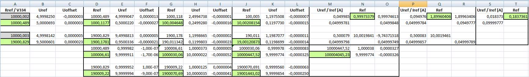
I calibrated my 5450A again, after one year, see column G
And again, the verification of 10M, 19M and 100M were way off, compared to the verification by 3458A, column I.


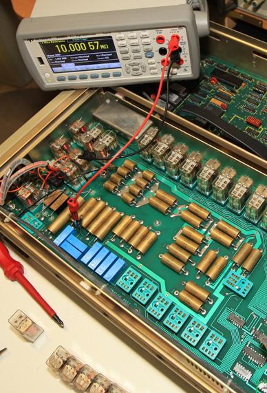
I opened the instrument, and measured these high Ohm values directly inside the unit, at the resistors, as indicated in the picture. The 5450A is set to OPEN, which de-energizes all relays.


From the measured values, "direct", in column K and M, you can see, that now all the high-Ohm readings were very well matching the before calibrated values.


As soon as I engaged the appropriate range, the readings dropped to the faulty values, between 50 to 300pm low. That's displayed in the picture above.

Therefore, there has to exist a leakage path inside the 5450A.

I de-soldered the high output/sense PTFE cables, as indicated here:


The measurement of the 100M stabilized much faster, but was faulty as before.
When unsoldering the cable to relay K30, the correct reading applied. K30 is open for the 100M Ohm range.

So I disassembled the K30 relay socket, and measured its leakage by applying 50V between two open contacts and monitoring the current, being <1pA. Therefore, the socket should have > 5 * 10^13 Ohm. In parallel to 100MOhm, that will create an error of a few ppm at most.

Anyhow, I cleaned the socket and its top and bottom area of the PCB with methyl alcohol. This did not yet cure the error.

So I investigated on relay K30.
Between isolated pins, @ 50V, I measured leakage currents on the order of 20..40pA, i.e. between two open relay contacts, between switch contact and guard (relay metal body), and between switch contact and coil contacts.
That gives leak resistors of about 10^12 Ohm each, giving an error for the 100MOhm resistor of several 100pm, as these paths add up.
It can also be observed, that the 5V digital supply may even source leakage currents into the network.


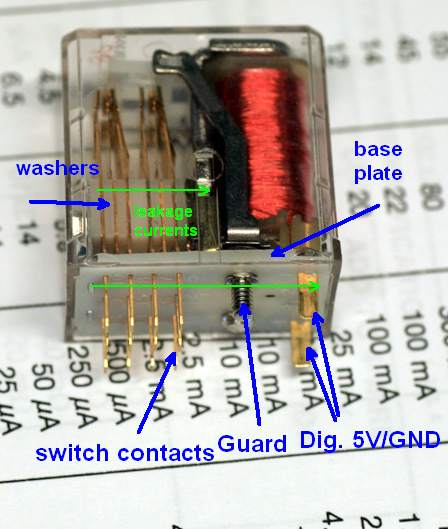
At a closer look on relay K30, you may see the base plate and the isolation washers, which are made from some plastic, which I assume not to be PTFE.
This plastic will give rise to the leakage currents across all the contacts, as indicated by the green arrows. I assume, that this plastic material contains filler / softening agent, which has outgassed or diffused after 30 years, and creates this leakage. Maybe the plastic material itself deteriorates, and the cracked products are conducting.

I disassembled the relay , removed the coil, and washed the contacts and base plate using benzine and methyl alcohol. This gave no improvement, the leakage currents remained the same.


The leakage of all mechanical relay K15..K20, K30 and K31 may affect the high Ohm readings.
If I pull these out, and engage the high Ohm ranges, the reading now will not drop any more.


Everybody can measure this summed leakage by applying 50V between case ground and guard. I observed about 450pA leakage current, so about 10^11 Ohm isolation only between analog and digital, and the resistor chain.. that's an order of 1000ppm error related to the 100M resistor.

The explanation, why it's possible to calibrate correctly, is indicated in the schematics. You see, that the 50V test voltage across 100M is divided to about 5V. The ratio between both voltage measurements gives the calibration ratio from 10M to 100M. The crucial leakage current does not affect the 100M resistor in this volt - measurement mode, but will definitely decrease its value during any normal resistance measurement.
There's only a leakage in parallel to the 10M resistor, which affects this ratio measurement, but an order of magnitude smaller, i.e. on the order of about 10ppm.


This error description is independent from brand of DMM and from measurement voltage, 10V or 100V, or else. So, even the highly prestigious 8508A will show the exact same error, in normal or in high voltage resistance mode.


So I conclude, that the HP instruments measure high Ohm very well, inside specification, or better.

The 5450A itself causes this fault in the high Ohm ranges. The same observations have been made for the instruments of eevblog (#544, 33:52 .. 34:10 min), PeLuLe, quarks, and mine, and maybe also by zlymex.

The Fluke PWW resistors are really great, but these mechanical relays suck.

Therefore, this is a systematic error after many years.

These relays may be un-obtainium as new.
Old stock is very expensive, I've seen about 80$ for 1 EA, but they will have definitely the same problem.
TYCO still offers these standard R10 relays, but isolation is specified the same, 10^11 Ohm, which is 3 orders of magnitude short.


In retrospect, the Fluke engineers faced the problem that these mechanical relays should isolate to 10^14 Ohm, but also would be able to carry up to 500mA of current. In this design, it was not possible to solve this contradiction. Maybe a look into the similar 5720A design might reveal, how it can be done better.
Or these newer instruments will face the same problem, after more than 10 years time.


To solve this problem in the 5450A, I think over separating higher and lower ranges by interrupting the path between the high ohm reed relays and the lower ohm mechanical relays, and connecting the high ohm ranges (1M ..100M) to the front jacks, and the lower Ohm ranges (1 Ohm .. 190 kOhm) to the rear.

Maybe later I'll find some really highly isolated reed relays, 5V coil and 100mA carriage current, to replace the failing relays.

Some final remarks about the  uncertainty of the calibration process.

I used the 5442A as a DCV source and the 3458A for the ratio measurements.
In the standard procedure, which follows the manual, the measured voltages and offsets were recorded in the calculation Excel-sheet, starting from my external 10k standard. The fields marked in green then display the calibrated value, which is consecutively used for the next upper/lower range.


As the 3458A may create additional leakage currents for the high Ohm ranges, I used an additional procedure, with two measurements for each resistance value, to cancel these DVM currents.
That gives very similar readings as the the standard process.


I also processed this latter method directly inside the open instrument, which also gave consistent results to the calibration from outside.
So I conclude, that the normal calibration process is really not much effected by the relays leakage.


Frank
« Last Edit: January 15, 2017, 09:14:20 am by Dr. Frank »
 
The following users thanked this post: quarks, dr.diesel, alm

Offline pelule

  • Frequent Contributor
  • **
  • Posts: 513
  • Country: de
  • What is business? It’s other people’s money
Re: EEVblog #544 - Fluke 5450A Resistance Calibrator Teardown
« Reply #109 on: January 14, 2017, 05:45:47 pm »
Great investigation  :-+ :-+
I did the last verification of my 5450A in Dec 2015 against 1281 & 3458A. Both DMMs showed similar readings and  also against in in Oct 2014 calibrated values.
My annual verification is due, thus I will check and report my findings.
Hope I don't have that issue (yet).
I guess your front/rear solution my suitable, but has disadvanmtages (I personally prever to stay as close as possible to original function to prevent mishandling).
How is the idea of following solution/fixing:
- use low leakage COTO relays mounted in a fly over the board solution
There should be enough room/volume in the 5450A
BR
PeLuLe
You will learn something new every single day
 

Offline Dr. Frank

  • Super Contributor
  • ***
  • Posts: 2425
  • Country: de
Re: EEVblog #544 - Fluke 5450A Resistance Calibrator Teardown
« Reply #110 on: January 14, 2017, 06:41:06 pm »
I guess your front/rear solution my suitable, but has disadvanmtages (I personally prever to stay as close as possible to original function to prevent mishandling).
How is the idea of following solution/fixing:
- use low leakage COTO relays mounted in a fly over the board solution
There should be enough room/volume in the 5450A
BR
PeLuLe
Yes, this splitting isn't nice, but it will be a reversible change.

COTO does not produce 10^14 Ohm insulating relays anymore, obviously.
Old stock costs 40$/EA.
But I also thought to do it like you propose, i.e. disassembling all affected mechanical relays and sockets, 8EA, I think, and assembling the reed relays hanging in the breeze.

Any other good ideas are welcome!
 

Offline pelule

  • Frequent Contributor
  • **
  • Posts: 513
  • Country: de
  • What is business? It’s other people’s money
Re: EEVblog #544 - Fluke 5450A Resistance Calibrator Teardown
« Reply #111 on: January 14, 2017, 10:01:17 pm »
I just wouldn't disassembe the relay sockets, if they are not affected (at least I understood your description of problem that way).
I would use the old relay contacts (only that), solder the connectiong wires to, and use it as plug-in to the sockets for the connection of the add-on card. So, in case you find by luck replacement parts, you could easy remove your changes.
An out of my view suitable alternative is DigiKey 374-1389-ND / EUR 13,74 + VAT
Hermetic sealed reed releay with high insulation relay coil, contact 100 TOhm (1e14) High Leakage Distance

I use that for my precision analog switching also.
BR
PeLuLe

PS: HP 3458A and Datron 1281 are warmin up to check the 5450A..
You will learn something new every single day
 
The following users thanked this post: leighcorrigall

Offline aronake

  • Regular Contributor
  • *
  • Posts: 232
  • Country: hk
Re: EEVblog #544 - Fluke 5450A Resistance Calibrator Teardown
« Reply #112 on: August 20, 2024, 10:04:37 am »
Reviving this super old thread.

I just got a 5450a. Great machine! Fits my needs very well.

I have noticed the impact of current leak on 10M and above.

My idea of solving this is to calibrate the 5450a with some other methodology than the internal ratio feature for higher resistances. Idea is to use 5450a internal ratio function up to 100K. Then some external stable 1M resistor (calibrated with ratio from certified 10K standard) to calibrate 5450a 1M, 10M, 19M and 100M.

1M to 100M may be too long of ratio to calibrate so may need a 10M in-between.

This take away the smart internal ratio calibration function of the 5450a but has the benefit of being a significantly better calibration and no need for any hardware hacks.


Offline Dr. Frank

  • Super Contributor
  • ***
  • Posts: 2425
  • Country: de
Re: EEVblog #544 - Fluke 5450A Resistance Calibrator Teardown
« Reply #113 on: August 20, 2024, 11:44:51 am »
Reviving this super old thread.

I just got a 5450a. Great machine! Fits my needs very well.

I have noticed the impact of current leak on 10M and above.

My idea of solving this is to calibrate the 5450a with some other methodology than the internal ratio feature for higher resistances. Idea is to use 5450a internal ratio function up to 100K. Then some external stable 1M resistor (calibrated with ratio from certified 10K standard) to calibrate 5450a 1M, 10M, 19M and 100M.

1M to 100M may be too long of ratio to calibrate so may need a 10M in-between.

This take away the smart internal ratio calibration function of the 5450a but has the benefit of being a significantly better calibration and no need for any hardware hacks.

I remember that somebody in this thread (?) has his 5450A been calibrated by an external precision bridge or another direct measurement method .. very tedious, but precise in 1st place.
That sounds similar to your approach..

Anyhow, these leaky relays are not stable at all, and may be very sensitive to humidity variations as well.
I observed big changes in the high Ohms ranges, between separate measurements, with the faulty relays.
That means you will initially calibrate your instrument successfully, but when doing a consistency check some time later, the high ranges will probably far off, due to these leakage variations, being due to to humidity variations, or further degradation of the plastics.

Also, you would need sophisticated test equipment for the complete calibration, and would not have the 'easy' possibility of making consecutive 10:1 / 1:10 transfers.

I'm pretty much interested in your method and your results, anyway.

Frank
 
The following users thanked this post: aronake

Offline aronake

  • Regular Contributor
  • *
  • Posts: 232
  • Country: hk
Re: EEVblog #544 - Fluke 5450A Resistance Calibrator Teardown
« Reply #114 on: August 20, 2024, 04:33:21 pm »

Anyhow, these leaky relays are not stable at all, and may be very sensitive to humidity variations as well.


Thats a good point.

Kind of unfortunate design choice to not keep the high ohm resistors in a separate circuit on an otherwise great machine despite being designed almost 50 years ago.

The 5450a I have was made in 1989. Last calibration, which seems to have been very seriously made, was done in 2007. My standard resistors are now at the national metrology laboratory for calibration. Once I get them back I will see how much or little the 5450a have drifted.
 

Offline aronake

  • Regular Contributor
  • *
  • Posts: 232
  • Country: hk
Re: EEVblog #544 - Fluke 5450A Resistance Calibrator Teardown
« Reply #115 on: August 20, 2024, 05:08:47 pm »
Any expert here on views on how to best connect a 3458a to the 5450a for 4 wire measurement?

Guard on 3458a open or to low?
Use cable between guard on 3458a to 5450a? For both wires or only sense or current?
Ext Guard switch on or off on the 5450a?


Offline aronake

  • Regular Contributor
  • *
  • Posts: 232
  • Country: hk
Re: EEVblog #544 - Fluke 5450A Resistance Calibrator Teardown
« Reply #116 on: September 04, 2024, 06:13:20 pm »
I have now had some more time to test mine a bit more.

It was last calibrated on 17th July 2007, so 17 years ago. The calibration sticker say PRIS T&M Calibration www.calibration.com. Www.calibration.com do not work anymore, and i think there may have been a character before PRIS that got cleaned away. Anyone who know what calibration lab this may have been? Then there is what looks like an extremely old Tektronix calibration sticker.

My measurements was done with a 3458a just calibrated against a 10K standard resistor comming straight out of the national standard and measurement with 0.3 PPM uncertanity at k=2. There is ofcourse a risk that the 3458a has a bit of in error in its artefact calibration, i have not been able to verify that, but I see no indication of it, so likely it should be quite precise. Measurements done with APER 1, average of 10 measurements, delay 1 and Ocomp on.

TC measurements was not really ideal, but should give a decent indication. My normal TEC box is all to small for a full size rack unit, so i took the cardboard box it came shipped in and cut a hole to place the lid of my normal TEC box that have the TEC elements. To give some more insulation the cardboard box was wrapped in a taoruketto. I placed a thermistor inside the resistor compartment of the 5450a to measure temperature. With this "TEC box arrangement" I could cool down the machine to 19 degrees while not running. Measurements was then done with the TEC slowing down the self heating of the machine and toward the end of the temperature sweep help to heat the machine. The sweep was 19 to 33 degrees (resistor compartment temperature) over 2 hours. At lab temperature (23 degrees) the 5450a keep around 29 degrees in the resistance compartment after being properly warmed up. So TC measurements are at the 29 degree point.

Here is my measurement data:


2361221-0

Observations:
- It seems my 5450a does not show symptoms of leakage. High resistances rather go up than down.
- I suspect that in the calibration, they did not get the transfer to 19K right, this has then propagate to become much worse for higher resistances. I marked these in yellow.
- Except for the 1.9x issue the machine show remarkable stability! Resistances 10 to 1K are all within 24h specification after 17 years!! All other (except high 1.9X) well within 1 year specification. Respect!
- TC is generally good, and in many cases excellent! I am impressed they got 1R to 1.11 PPM/C with just one wrapped resistor. The 1.9M resistance point is pretty bad though.
- The last 81M resistor for the 100M point is a remarkable piece of 1970ies engineering. Sure, a bit of TC but has been a big contributor to keep the machine below 24h accuracy after 17 years. Actually, I think the whole machine is quite remarkable. Particularly if being lucky and get a non leaky variant.

Plans from here:
- Do a new proper calibration of all resistors.
- The thermistor is permanently installed inside the resistance department. So plan is to write python code so that when I use the 5450a, I do not only take most resent calibration value, but also adjust it for TC when doing calibration scripts to add some accuracy.
- I haven't gotten to check the TC marking of the resistors, but will do that and compare with my measurements.
- Get a bigger and better TEK box so I can do more proper TC measurements. Longer time, up and down.
« Last Edit: September 04, 2024, 06:15:30 pm by aronake »
 

Offline aronake

  • Regular Contributor
  • *
  • Posts: 232
  • Country: hk
Re: Fluke 5450A - Mysterious problem identified, not yet solved
« Reply #117 on: September 06, 2024, 09:46:23 am »

Everybody can measure this summed leakage by applying 50V between case ground and guard. I observed about 450pA leakage current, so about 10^11 Ohm isolation only between analog and digital, and the resistor chain.. that's an order of 1000ppm error related to the 100M resistor.


I see a leakage between ground and guard of around 100pA at 50V. Much better than 450pA, but still somewhat concerning.


Share me

Digg  Facebook  SlashDot  Delicious  Technorati  Twitter  Google  Yahoo
Smf