Ah alright that's what is bothering you, alright fine il do some drawing too.
What's bothering me is that people don't understand electromagnetism and don't want to learn it. And keep coming up with all kinds of pseudo scientific excuses just to try to make their pseudo scientific theory work. This is an insult to serious engineering and is below the level of dignity of this forum.
We're not here to propagate pseudo-science.
By the way bsfeechannel two of your batteries are drawn backwards (Botton inner two)
I've corrected the picture, thank you, but it won't make any difference. That doesn't in any way model Lewin's circuit because those voltages are not there. It's just an invention to try to cheat Maxwell and make it look as if Kirchhoff always holds.
So since we are so bothered with how the magnetic field affects things other than wires in the circuit lets fix that by putting the major wires into a shielded box.
Varying magnetic fields do not affect wires. This is something you don't understand. The electrical field inside a wire is ZERO. So wires don't care about varying magnetic fields.
It is the path
outside the wire that produces a voltage.
I'll repeat:
IT IS THE PATH O U T S I D E THE WIRE THAT PRODUCES A VOLTAGE under a varying magnetic field.And if there is not a varying magnetic field in an area defined by a wire and some path outside that wire, the voltage is ZERO.
This box has infinitesimally small holes to conveniently get out wires out of it and is made out of a superconducting material or a material with an infinite permeability. This makes it impossible for the field inside to escape, but because magnetic monopolies are not possible in our universe means that the upwards flux must close itself somewhere. A superconducting box would get eddy currents induced on the inside that produces this opposite downwards flux in the walls, or in the case of an infinite permeability box the field lines would just follow the path of least resistance along the inner surface of the box to flow back down.
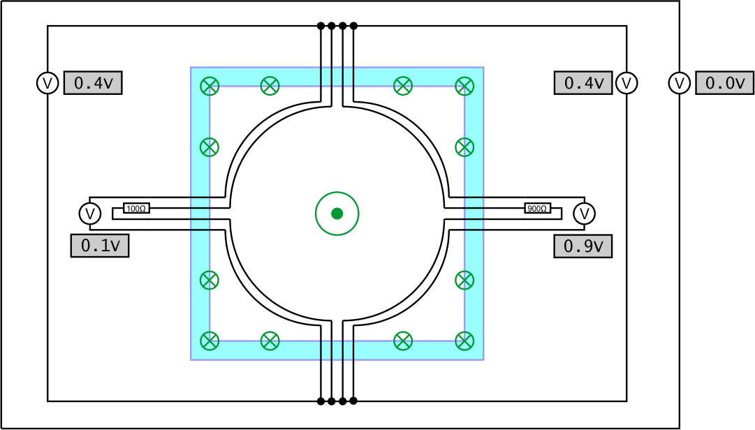
For convenience i also added some voltmeters around the scene. I think all of you will agree with the readings they are showing. Notice that the rightmost voltmeter is showing zero because the sum magnetic field outside the box is zero (If it was showing anything else than we don't have an ideal shielding box).
So since the field is contained and the box contains nothing else but coupled inductors we can turn it into a ideal transformer and all the voltmeters still show the same readings (Follow each path and add it up if you don't believe me)

This shows that an ideal transformer can behave like the above circuit when it is in a box, something that shouldn't be surprising.
In this case your modelling is absolutely correct because THIS is a lumped circuit. All the magnetic field is confined outside the area of the circuit. Provided that your voltmeters do not invade the area of the "box", you can place them anywhere.
Okay but we don't actually have this magical ideal shielding box. So lets look at what would happen if the box was removed?
Well unsurprisingly the most inner voltmeters that used to show 0.1V and 0.9V would show the same value. The path trough them does not enclose any extra flux so there is no reason for them to show something different. This now completes the chain, the circuit behaves like a transformer even if we don't contain the fields.
Where things do get messed up is all other voltmeters. The magnetic field is now affecting all there probe wires and as a result affecting the voltmeter readings. If we wish to continue doing circuit analysis then the model has to be updated to give those wires correct coupled inductance too, after that the voltmeter readings from circuit analysis will once again match the real thing.
Any objections to this explanation?
A lot. This is where you, Mehdi and co., fail miserably. When you remove the box you destroy your transformer. The lines of the magnetic field will return elsewhere. You do not have a lumped component anymore, much less a coupled inductor. But you insist that there must be some kind of error, because the transformer must still exist somehow. After all, what is a transformer? Is it not made of a piece of wire? Well the wire is there, so there must be a transformer too.
Wrong. The wires couldn't care less about the varying magnetic field.
And i still don't see what part of Maxwell i supposedly don't understand. All of this makes perfect sense to me from the point of view of Maxwell or from the point of view of mesh circuit analysis.
It makes perfect sense to you because your Maxwell is not the real Maxwell. With your Maxwell, the voltages of a circuit must always add up to zero.
With the real Maxwell, voltages may or may not add up to zero, depending on a series of conditions.
Where do the explanations above violate Maxwell?
Here and I quote:
This now completes the chain, the circuit behaves like a transformer even if we don't contain the fields.
Where things do get messed up is all other voltmeters. The magnetic field is now affecting all there probe wires and as a result affecting the voltmeter readings. If we wish to continue doing circuit analysis then the model has to be updated to give those wires correct coupled inductance too, after that the voltmeter readings from circuit analysis will once again match the real thing.This is bullshit. The magnetic field does not affect the probes nor the voltmeter readings. No coupling occurs. No correction is needed.
This is not Maxwell.
The real thing is what the voltmeters are reading.
You're trying to find facts to support your a-priori conclusions. This how religion works, not science.
Sorry if it sounds rude but i get the feeling that you two understand Maxwell perfectly well but have some issues understanding circuit analysis and circuit modeling.
Circuit analysis is just a special case of Maxwell. If you say that we understand Maxwell, you're saying that we understand circuit analysis perfectly well.
And you have a serious problem with circuit modeling, because you see voltages where they aren't.


