Alright, so I've been playing with electronics for more than a couple of months, but just built stuff on a breadboard and took it down, and built something else, took it down, repeat... I've been trying to learn about this stuff so that explains my lack of tangible output.
Anyway, so I'm trying to become more experienced with arduino so I can do some really cool things, and I was sick of having my Uno board next to my breadboard with a bundle of wires connecting the two, so I decided to built my own usb-serial adapter based on the FTDI FT232RL. So I ordered the parts and built one according to sparkfun's schematic. The main difference is that, on their's, they had a solder jumper to select between 5V and 3.3V. I didn't like that, so I put a small switch in from my junk box.
This is my first perf-board layout so go easy on me

Well actually I would prefer that you tell me what I did wrong so I can improve next time. (I.E.
constructive criticism requested. )
Here are the pictures...
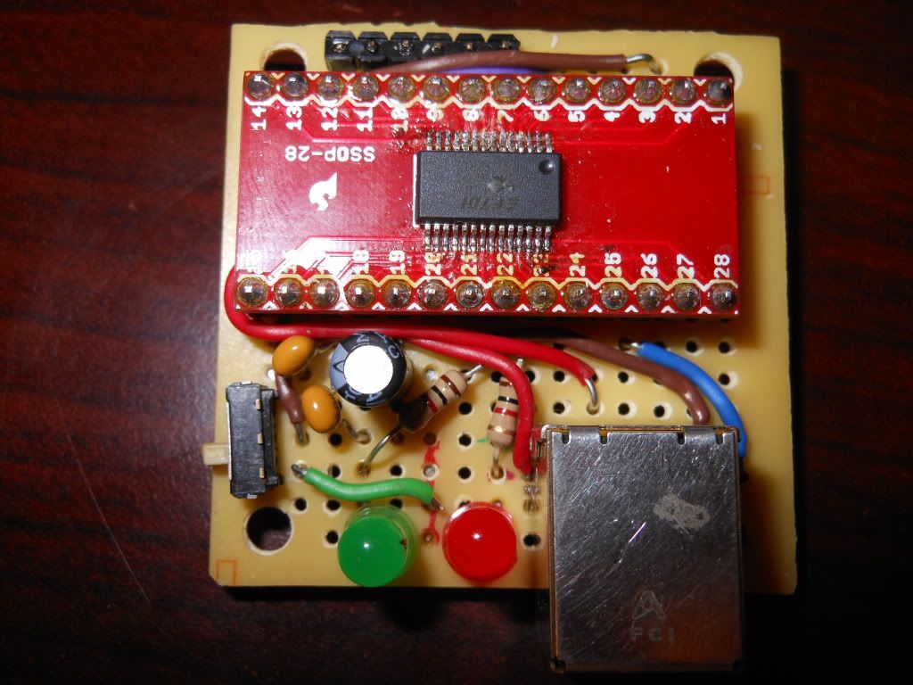
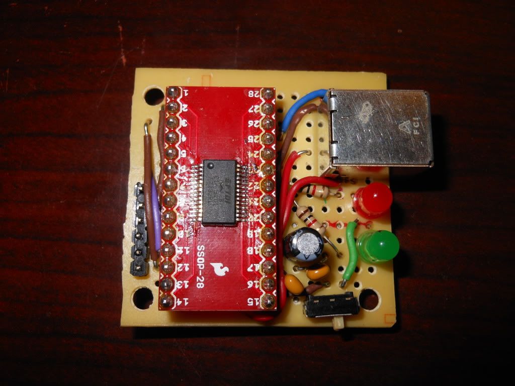
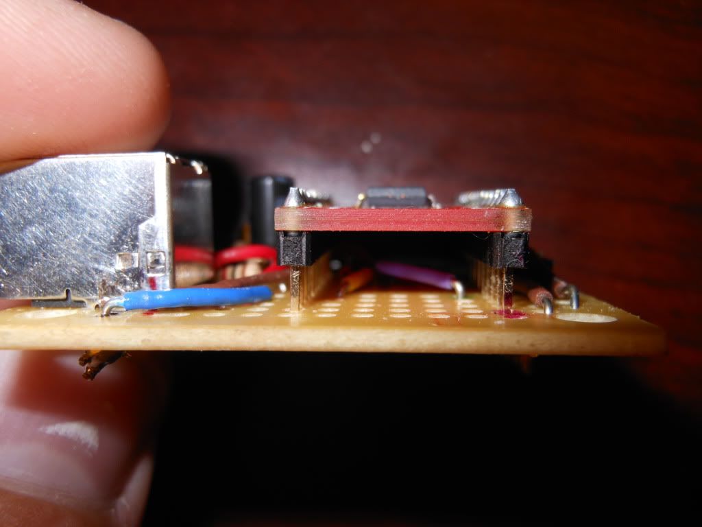
You probably noticed that I raised the SSOP breakout board up off the perf board. This is so I could route wires underneath for a cleaner layout.
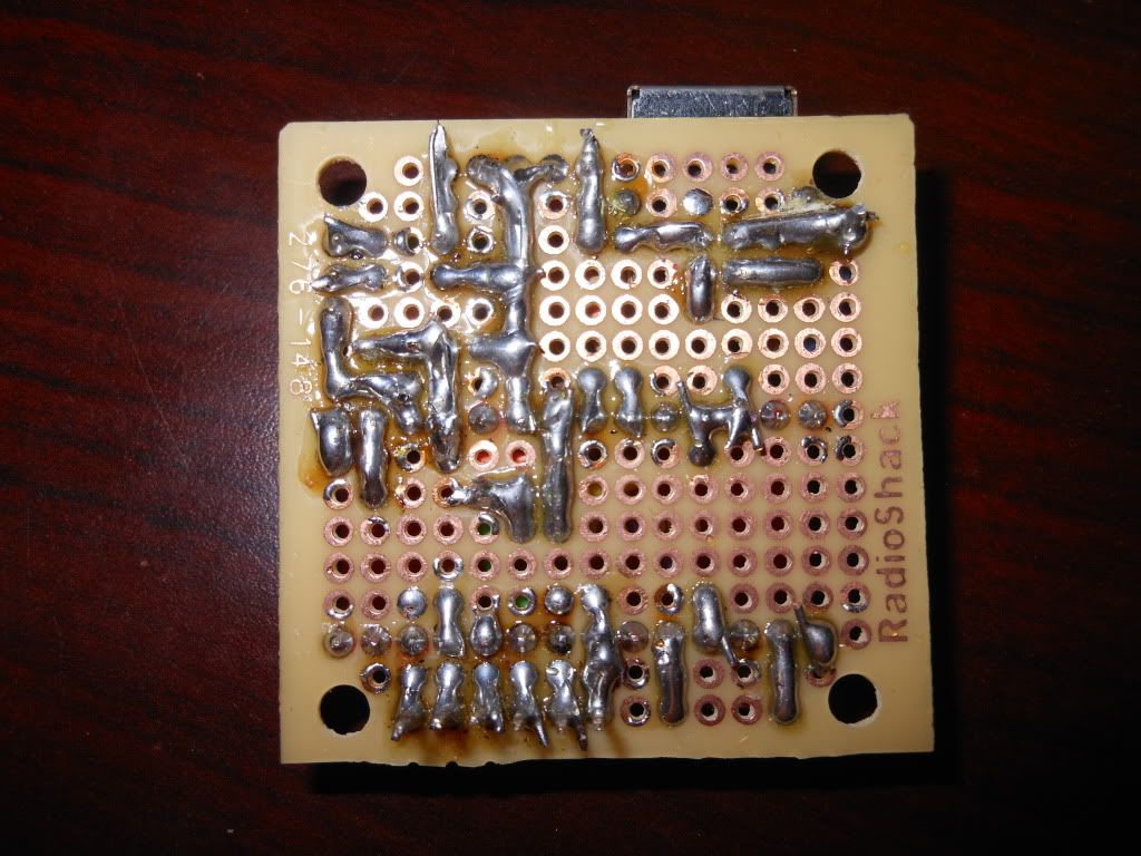
I have seen alot of people's perfboards, and the solder bridges underneath. I always thought they just made the connection across pads with just the solder. I discovered very quickly that this wasn't the case, and that you actually bend the leads over and then solder.
Of course, It didn't work at first.

I then discovered, while troubleshooting, that I had forgot to connect the USB D- and D+ lines to the FT232. I fixed that with the two red wires, that don't look as nice as the others. That kind of irritated me because I like stuff to look nice. It works now though! I just got done programming my first arduino program with it. YAY!
Anyway, tell me what you think!
Joshua


