Author Topic: A problem in a high speed PCB  (Read 2175 times)

0 Members and 1 Guest are viewing this topic.

Offline xzswq21Topic starter

  • Frequent Contributor
  • **
  • Posts: 295
  • Country: 00
A problem in a high speed PCB
« on: October 05, 2018, 09:21:01 pm »
Hello
I have a PCB that a part of one of the high speed lines is not placed over the ground plane. the length is 1300 mils
actually it's LSB line of a high speed DAC (200MHz, 3.3V logic, the input capacitance of the DAC is 5pF).
is there any solution to repair it?

https://drive.google.com/open?id=1Em9Ov9_iE4yF5cVNMjFvx8r7M0IeYgcg


as usual we have a 22 OHM resistor at the input of the line. can I replace 22 ohm with a 75 or 100 OHM resistor at the input of this line to reduce any ringing or overshoot? or can I scratch a part of this line and solder a 0402 resistor, for example here:

https://drive.google.com/open?id=1ctwwOy-jWaZ-Q58fG6jOD9G_WamF4Cai


Thanks
« Last Edit: October 05, 2018, 09:27:34 pm by xzswq21 »
❤ ❤
 

Offline KrudyZ

  • Frequent Contributor
  • **
  • Posts: 277
  • Country: us
Re: A problem in a high speed PCB
« Reply #1 on: October 09, 2018, 10:25:52 am »
I would measure the actual impedance with a TDR.
Then you can fix this to a fair degree by increasing the source termination resistor (your 22 Ohm) to match the line.
Make sure you subtract the output impedance of the driver chip.
Assuming you have sufficient setup time for the DAC, you should be OK. 1.3" is not all that long for a 200 MHz data feed.
To verify you would need a very low capacitance probe right at the DAC with minimal ground to tip separation and feed length, else the probe forms a stub and you are no longer measuring the circuit itself.
 
The following users thanked this post: xzswq21

Offline Feynman

  • Regular Contributor
  • *
  • Posts: 192
  • Country: ch
Re: A problem in a high speed PCB
« Reply #2 on: October 09, 2018, 09:24:27 pm »
Do you actually encounter problems due to the impedance discontinuity and resulting reflections?
 
The following users thanked this post: xzswq21

Offline xzswq21Topic starter

  • Frequent Contributor
  • **
  • Posts: 295
  • Country: 00
Re: A problem in a high speed PCB
« Reply #3 on: November 23, 2018, 06:50:47 pm »
I would measure the actual impedance with a TDR.
Then you can fix this to a fair degree by increasing the source termination resistor (your 22 Ohm) to match the line.
Make sure you subtract the output impedance of the driver chip.
Assuming you have sufficient setup time for the DAC, you should be OK. 1.3" is not all that long for a 200 MHz data feed.
To verify you would need a very low capacitance probe right at the DAC with minimal ground to tip separation and feed length, else the probe forms a stub and you are no longer measuring the circuit itself.

Do you actually encounter problems due to the impedance discontinuity and resulting reflections?

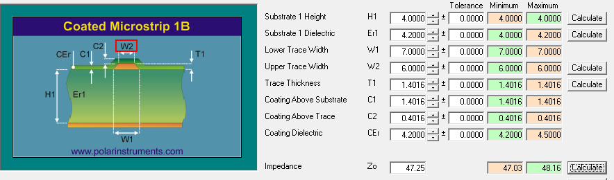
Actually to have 50 OHM impedance, the distance should be 4 mils.


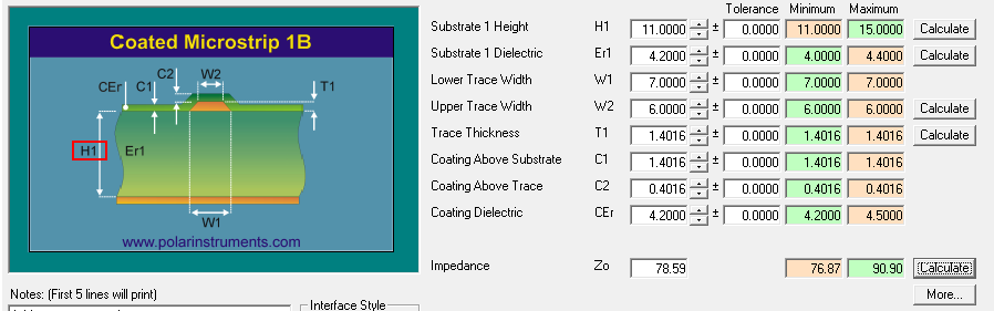
so I have dug a slot under the line and very close to the line, now the distance is around 11 mils (now I can see some ground planes! I didn't cut them).
then I have placed a copper shield in this slot (I have cut some shield from a RG-316 cable) so I soldered the shield to the near ground planes.

on the other hand I have increased the damping resistor from 22 OHM to 50 OHM.
I calculated the C and L and then modeled the lines as a lumped model in LTspice. I checked some situations, the overshoot of the line is in range (I checked the maximum allowed DAC's input logic level) and the rise time is good. for example with a 33 OHM resistor the level of overshoot is out of allowed DAC's input logic level.

I know it's not perfect but better than that situation.
« Last Edit: November 23, 2018, 06:54:32 pm by xzswq21 »
❤ ❤


Share me

Digg  Facebook  SlashDot  Delicious  Technorati  Twitter  Google  Yahoo
Smf