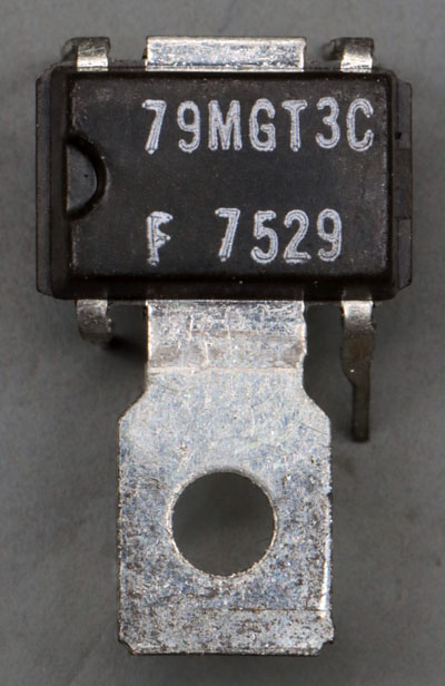
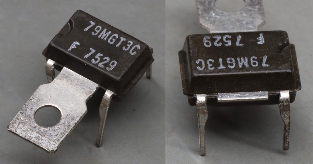
The µA79MG corresponds functionally to the µA78MG, but regulates a negative voltage. The output voltage can be set between -2.2 and -30V. The Power Mini Dip package was available in three versions: T-1, T-2 and T-3. The µA78MG documented here uses the T-2 variant, which has a angled metal tab on each side. The µA79MG shown here uses the T-3 variant, which only has one straight metal tab. In the T-1 variant, two metal tabs are bent downwards so that they can be soldered to the circuit board.
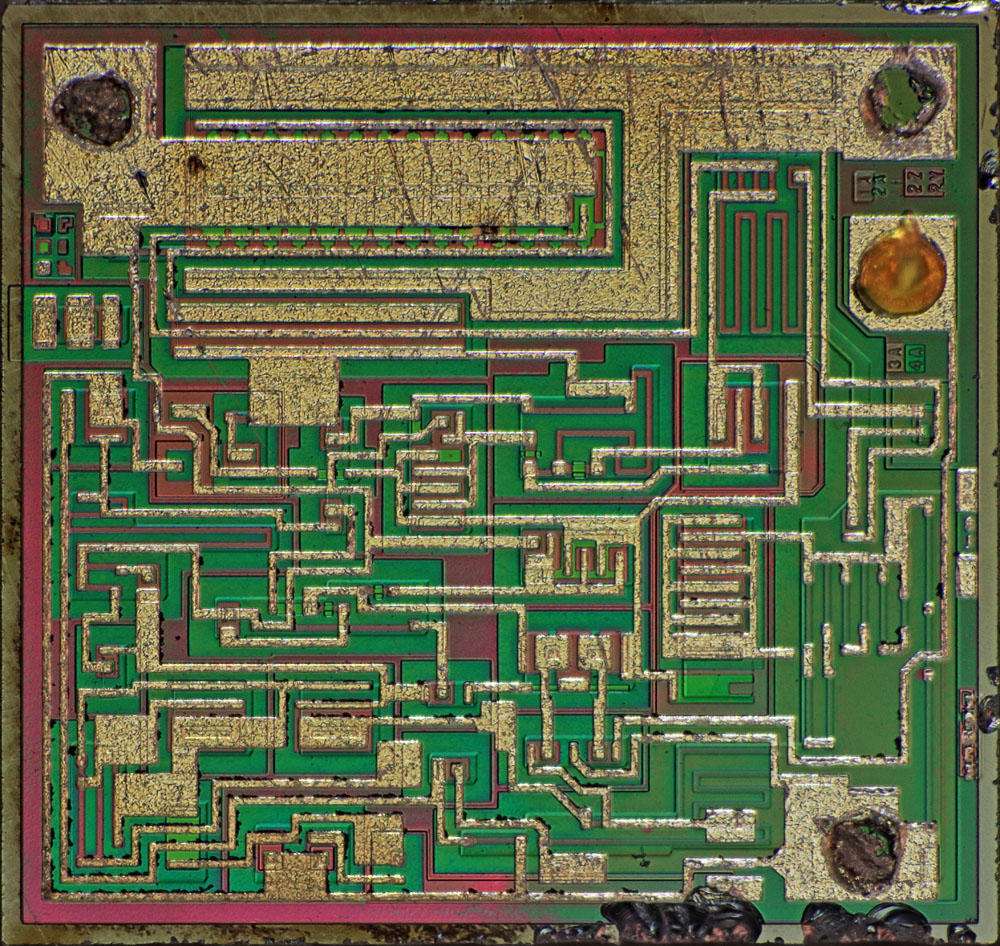
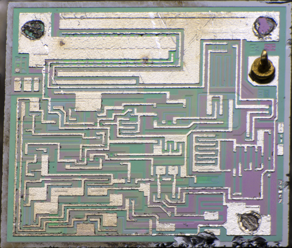
The dimensions of the die are 1,9mm x 2,0mm.
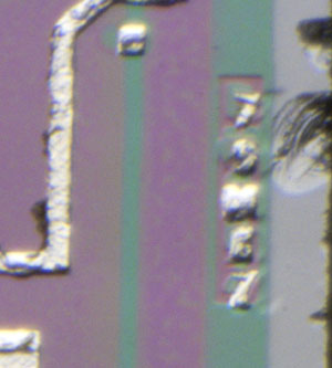
Several masks are depicted on the right edge. In the lower area there is a character string which is presumably 79MGZ.
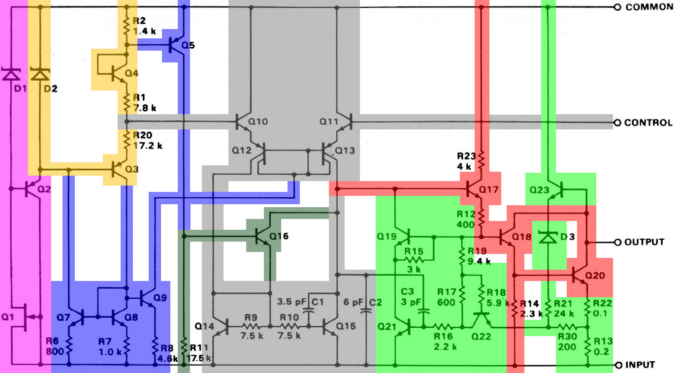
The datasheet shows the typical circuit of a 79xx voltage regulator. The operation of the circuit is described with the Mikroelektronika Botevgrad 7915 (
https://www.richis-lab.de/voltageregulator20.htm). The µA79MG differs from this only in minor details.
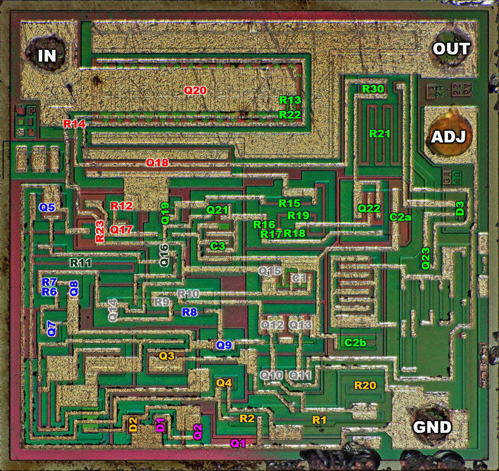
The circuit on the die corresponds to the illustration in the circuit diagram. A series of resistors are integrated in the right-hand area, which can be used to represent a fixed-voltage regulator. To the left of these resistors is an unused capacitor, which probably stabilises the feedback loop.
The capacitor C2 appears to be divided into two areas. The n-doped buried collector is used, which represents the desired capacitance with the p-doped substrate.
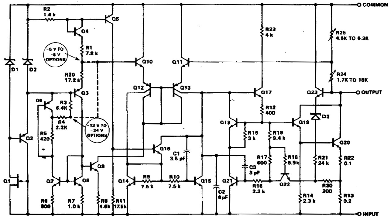
A transistor and a few resistors are integrated in the bottom left corner of the µA79MG, which have no effect on the circuit. The Fairchild Voltage Regulator Handbook from 1978 contains the circuit diagram of the µA79M00 fixed-voltage version. There, the additional components are used to represent a different tapping of the reference voltage for the higher output voltages. The higher reference voltage ensures that the feedback voltage divider does not reach too extreme resistances at high output voltages, which worsens the control behaviour. In order to be able to display the full output voltage range with the µA79MG, the low reference voltage must be selected.
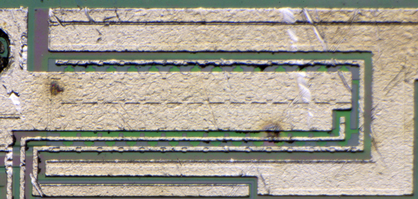
There are two discolourations in the power transistor which indicate that the voltage regulator was defective.
https://www.richis-lab.de/voltageregulator28.htm 


 Recent Posts