Author Topic: [Volt-nut] "HULK" Fluke 5720 calibrator rig build out of random broken boards.  (Read 41063 times)

0 Members and 1 Guest are viewing this topic.

Offline Echo88

  • Frequent Contributor
  • **
  • Posts: 826
  • Country: de
Now that is some serious dedication!  :-+
 

Offline dl1640

  • Regular Contributor
  • *
  • Posts: 222
  • Country: cn
Nice surgery! Be sure to check the insulation resistance
 

Offline TiNTopic starter

  • Super Contributor
  • ***
  • Posts: 4543
  • Country: ua
    • xDevs.com
Digikey parts arrived today. Among others I've ordered single-component heat-cure epoxy to fill the carved parts of PCB material. It worked quite nicely for first ever try.  :)


Measured resistance between affected windings >1GOhm, no issue there.

Also some other random parts, including brand new Sunon Maglev 92mm fans. I want to make this second calibrator quieter than first one, since it will not have high voltage A14/A15 boards I guess it could run lower speed fan as well.

« Last Edit: April 25, 2019, 12:42:09 pm by TiN »
YouTube | Metrology IRC Chat room | Let's share T&M documentation? Upload! No upload limits for firmwares, photos, files.
 

Offline wolfy007

  • Regular Contributor
  • *
  • Posts: 228
  • Country: au
  • Back into electronics again, as a hobby this time.
Never tried one part epoxy, how was it to work with (thick or runny)? Was there any hardening before applying of heat to cure?
 

Offline TiNTopic starter

  • Super Contributor
  • ***
  • Posts: 4543
  • Country: ua
    • xDevs.com
It's like icecream. I squeezed a bit of it to the spot and used toothpick to fill all the gaps and voids. It's not runny, rather easy to apply without going all over the place. Since it specified to have 2 year shelf life at room temp (22C) there is no hardening without heat. I've cooked board area at about 90-100°C for 30 minutes. It got semitransparent after cure, and hardness of soft type plastic, like ABS. Photo above shows state before cure.

I've tested board after epoxy at 1000VDC, leakage about few tens nanoamps between affected signals. There was no guarding or shielding during test, so I'd say no problems for this particular application. 
YouTube | Metrology IRC Chat room | Let's share T&M documentation? Upload! No upload limits for firmwares, photos, files.
 
The following users thanked this post: bsw_m, wolfy007

Offline dl1640

  • Regular Contributor
  • *
  • Posts: 222
  • Country: cn
Quote
I want to make this second calibrator quieter than first one, since it will not have high voltage A14/A15 boards I guess it could run lower speed fan as well.

It looks the 2nd one is 732C + 1 \$\Omega\$ & 10k \$\Omega\$ standard  :popcorn:
 

Offline TiNTopic starter

  • Super Contributor
  • ***
  • Posts: 4543
  • Country: ua
    • xDevs.com
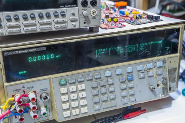
Sudden saturday morning livestream got some progress on "Hulk-2" 5700A calibrator.


I've got it all together to do first calibration attempts. Of course, there should be many hidden issues in this unit, so I don't expect that calibration to stay very long.
Also for more fun, I've used first 5720A calibrator as calibration source for today.


Also upgraded firmware to 5700EP version, which brings GPIB command level to 5720A. This is helpful for me, so I can keep using same python app, developed mostly for 5720A to do more tests in future.
Had to format calibration EEPROM, which is not a problem. Original data in EEPROM is for some other 5700A anyway, not this random mix of board.


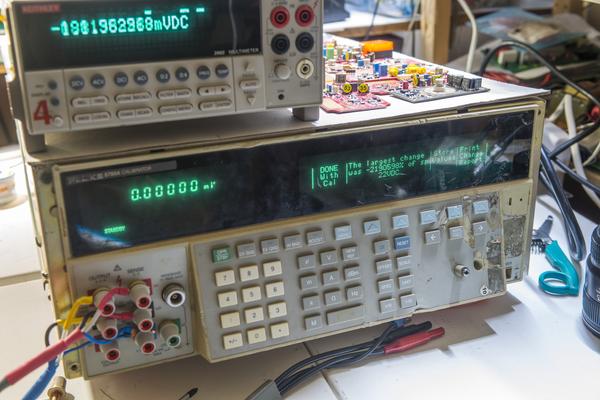
Calibration value shift is only -2190598% off the 24-hour calibrator spec.
No worries, she'll be alright.  :-DD

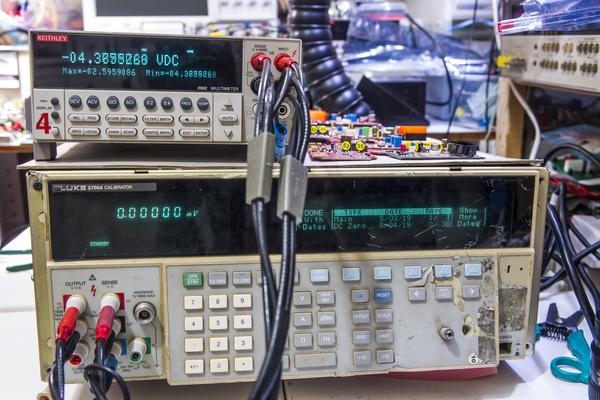
Keithley 2002 will be used as a check standard here.
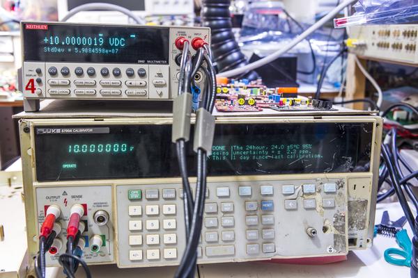
And we got long desired 10V out of the box. Only +0.2ppm off K2002 reading (which is calibrated last year July).


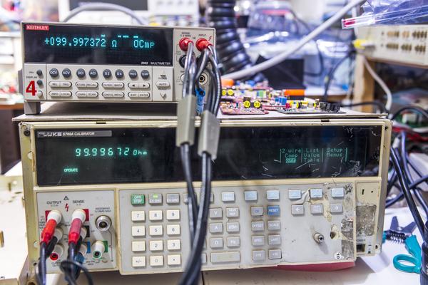
Resistance is nice and happy too. 10 Ohm is +0.2ppm, 100 Ohm is +6.5 ppm.


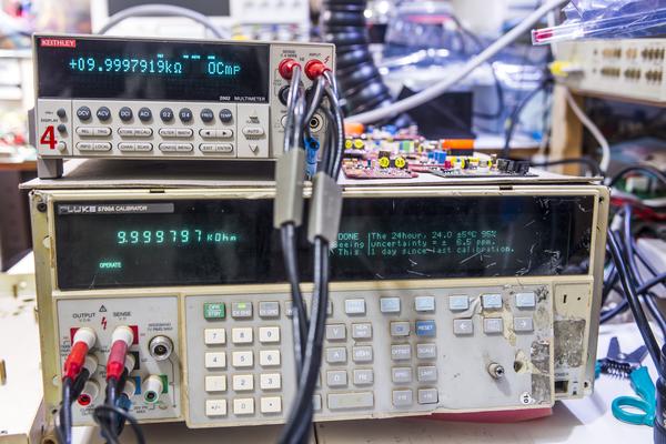
10 kOhm difference is -0.51 ppm. Calibrator specification for this resistance is +/-6.5 ppm.
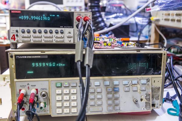
Also 100 kOhm is +0.2ppm.


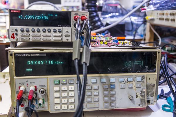
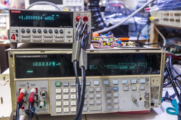
Even 1 Meg is mere -3.2 ppm, very happy with results so far on resistance. Not so much on DCI, there is 330 ppm error (which I expected, A7 current board known to have issue)


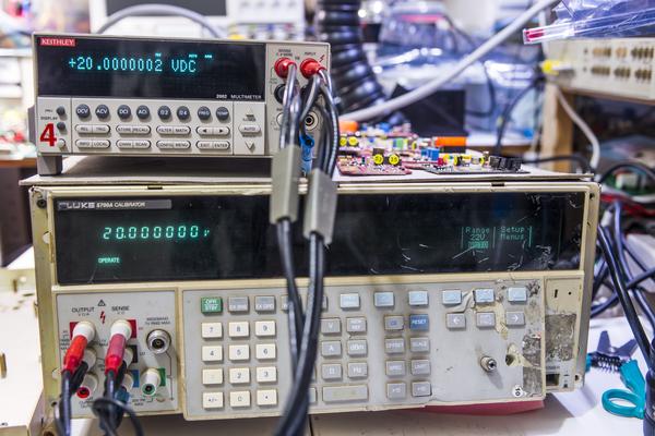
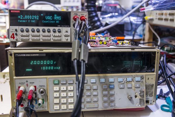
Look at that 20 DCV. Isn't it wonderful? ACV quick check also confirmed operation. Will use Wavetek 4920M AC Voltage Standard for more detailed tests on ACV when DCI issues fixed.
YouTube | Metrology IRC Chat room | Let's share T&M documentation? Upload! No upload limits for firmwares, photos, files.
 
The following users thanked this post: quarks, ManateeMafia, Dr. Frank, e61_phil, kj7e, hwj-d, syau

Offline HighVoltage

  • Super Contributor
  • ***
  • Posts: 5473
  • Country: de
Impressive as always !
There are 3 kinds of people in this world, those who can count and those who can not.
 

Offline TiNTopic starter

  • Super Contributor
  • ***
  • Posts: 4543
  • Country: ua
    • xDevs.com
Time to look at A7 assembly, which I already confirmed drifty from last year tests. This assembly perform two functions - generate frequency for ACV/ACI function, as it have high-resolution oscillator circuit. Second function is to voltage to current conversion, to generate 220uA/2.2mA/22mA and 220mA DCI/ACI current ranges. And this is where the problem is - all current ranges have drift about -400 or more ppm per 24 hours. I've checked relays, opamps and input signals - those are all good.


Same on 220uA range:


So the suspect is magic Fluke resistor network which sits in front of a complimentary drive hybrid assembly. Network have two isolated resistor 4K/40Kohm networks.


I've measured one side as 4.000K/40.000K but other side was 3.998K/40.248K. That made me thinking this other side have a drift, as this network is hermetic and laser trimmed.
Close look:


To test the theory, I've removed network and replaced one side with two BMF resistors for a test (actually three, 2x2K in series + 40K VHP102L from dead 3458A :)


Logging started, will see if current drift goes away. In that case I will need to find permanent solution for Z1 network replacement.
YouTube | Metrology IRC Chat room | Let's share T&M documentation? Upload! No upload limits for firmwares, photos, files.
 
The following users thanked this post: quarks, ManateeMafia, e61_phil, doktor pyta, Pipelie

Offline Pipelie

  • Regular Contributor
  • *
  • Posts: 172
  • Country: cn
Congrats
look like Hulk2 is all fixed now. :-+
 

Offline MiDi

  • Frequent Contributor
  • **
  • Posts: 600
  • Country: ua
What could be the cause for this partial fail of resistor network?
Degradation of junction between resistive material and lead?
 

Offline TiNTopic starter

  • Super Contributor
  • ***
  • Posts: 4543
  • Country: ua
    • xDevs.com
They keep coming, I couldn't help it :(


 :palm:
YouTube | Metrology IRC Chat room | Let's share T&M documentation? Upload! No upload limits for firmwares, photos, files.
 

Online Kleinstein

  • Super Contributor
  • ***
  • Posts: 14199
  • Country: de
What could be the cause for this partial fail of resistor network?
Degradation of junction between resistive material and lead?
From the picture the network looks rather bad - like flaws from the production:  It looks like there are parts of the TaN resistive layer missing, especially for the right divider) and in the area between the gold traces there seem to be still some blue resistor layer left. This network should have not passed QC.
 
The following users thanked this post: MiDi

Offline branadic

  • Super Contributor
  • ***
  • Posts: 2390
  • Country: de
  • Sounds like noise
I can't see parts of the TaN resistive layer missing, but a fine insulation groove instead, to form the resistive element and some dust on the top of the glass.

Edit: Looking more carefully it seems there is some small crack in the glass (upper right side) which leads to some humidity inside the package and which also changed the color of the golden traces.

-branadic-
« Last Edit: July 18, 2019, 07:09:01 am by branadic »
Computers exist to solve problems that we wouldn't have without them. AI exists to answer questions, we wouldn't ask without it.
 
The following users thanked this post: MiDi, FransW

Offline MiDi

  • Frequent Contributor
  • **
  • Posts: 600
  • Country: ua
The confusing thing is that all this visible flaws are on the good right half.
I could not find any visible flaws on the drifting left half...

The background why I asked was more if there is a common failure scheme with this type of resistors and if drifting DACs - specifically U180 - from 3458A suffers from the same.
 

Offline branadic

  • Super Contributor
  • ***
  • Posts: 2390
  • Country: de
  • Sounds like noise
Quote
The background why I asked was more if there is a common failure scheme with this type of resistors and if drifting DACs - specifically U180 - from 3458A suffers from the same.

Propably not, different resistor technology, different package, so the cause for drifty U180 might be different.

-branadic-
Computers exist to solve problems that we wouldn't have without them. AI exists to answer questions, we wouldn't ask without it.
 

Offline TiNTopic starter

  • Super Contributor
  • ***
  • Posts: 4543
  • Country: ua
    • xDevs.com
Hulks are getting their new Pelican travel cases :-+
No expense spared on precious Fluke ppms.


Models are 1690 and iM3075. I wanted two 1660's which are the perfect size for 5720/5725A, but local Peli rep did not have 1660 in stock.
« Last Edit: August 14, 2019, 03:27:36 am by TiN »
YouTube | Metrology IRC Chat room | Let's share T&M documentation? Upload! No upload limits for firmwares, photos, files.
 

Offline dl1640

  • Regular Contributor
  • *
  • Posts: 222
  • Country: cn
Re: [Volt-nut] "HULK" Fluke 5720 calibrator rig build out of random broken boards.
« Reply #167 on: September 22, 2019, 03:31:17 am »
Hi,

Did you replace electrolytic caps on A18 card?
My 5700A II output tripped above 22V range, its A18 has not enough voltage such as unregulated +480V is down to 300V.
Fluke repair center is no longer fully support 5700A  |O
 

Offline TiNTopic starter

  • Super Contributor
  • ***
  • Posts: 4543
  • Country: ua
    • xDevs.com
Re: [Volt-nut] "HULK" Fluke 5720 calibrator rig build out of random broken boards.
« Reply #168 on: September 22, 2019, 05:02:36 am »
Yes, of course. All electrolytic capacitors on every board and all CC resistors were replaced, because my units run 24/7, often unattended for many days..
YouTube | Metrology IRC Chat room | Let's share T&M documentation? Upload! No upload limits for firmwares, photos, files.
 

Offline ManateeMafia

  • Frequent Contributor
  • **
  • Posts: 730
  • Country: us
Re: [Volt-nut] "HULK" Fluke 5720 calibrator rig build out of random broken boards.
« Reply #169 on: September 23, 2019, 12:08:05 am »
dl1640,

sounds like one of the larger CC resistors may be shorted. I have found this to be true on a couple of A18 now. These are the ones connected to the high voltage zeners.
 

Offline dl1640

  • Regular Contributor
  • *
  • Posts: 222
  • Country: cn
Re: [Volt-nut] "HULK" Fluke 5720 calibrator rig build out of random broken boards.
« Reply #170 on: September 29, 2019, 08:33:48 am »
I took the board out of the box, checked R208 R210 R235 R236 (220k 3W), all good.  :-//
Maybe I'll have to desolder these big caps and test them...
 

Offline Laurent G

  • Newbie
  • Posts: 3
  • Country: fr
Hello, i wish know anymore on this shiel please. How is connect (on Guard, ok, but is it connect on other plug? or cable?)? And, it's here for what expectation? on DC Voltage, for emf? or AC voltage, and reduce noise?
Thaks a lot for the information ...


Share me

Digg  Facebook  SlashDot  Delicious  Technorati  Twitter  Google  Yahoo
Smf