Author Topic: #2000 Post : Teardown and study of Fluke 5700A Calibrator [56K warning!]  (Read 40063 times)

0 Members and 1 Guest are viewing this topic.

Offline Cerebus

  • Super Contributor
  • ***
  • Posts: 10576
  • Country: gb
Well, I've decided to build zombie 5700A out of nothing  :)

You're just a glutton for punishment aren't you? Any reasonable man would have been adequately chastised by that 3458A.  :)
Anybody got a syringe I can use to squeeze the magic smoke back into this?
 

Offline Echo88

  • Frequent Contributor
  • **
  • Posts: 826
  • Country: de
"Reasonable"...yeah, not a word you would use to describe a voltnut. Did you stop developing your own backplane-pcb for the PWM-DAC TiN?
 

Offline TiNTopic starter

  • Super Contributor
  • ***
  • Posts: 4543
  • Country: ua
    • xDevs.com
I still might need to do it, as it's unlikely that backplane will be for sale on fleabay. But it will have ports for all boards instead of DAC only. :) oh well.


« Last Edit: April 13, 2017, 01:01:14 am by TiN »
YouTube | Metrology IRC Chat room | Let's share T&M documentation? Upload! No upload limits for firmwares, photos, files.
 

Online TheSteve

  • Supporter
  • ****
  • Posts: 3752
  • Country: ca
  • Living the Dream
If TiN gets anymore out of control we're going to have to start a GoFundMe account to just pitch in and get him a 5700A.
VE7FM
 

Offline ManateeMafia

  • Frequent Contributor
  • **
  • Posts: 730
  • Country: us
Maybe an airline ticket to Everett so he can go dumpster diving?
 

Offline TiNTopic starter

  • Super Contributor
  • ***
  • Posts: 4543
  • Country: ua
    • xDevs.com
I can soon have own dumpster, thank you.  :P

Schematics for backplane board in progress :)
YouTube | Metrology IRC Chat room | Let's share T&M documentation? Upload! No upload limits for firmwares, photos, files.
 

Offline TiNTopic starter

  • Super Contributor
  • ***
  • Posts: 4543
  • Country: ua
    • xDevs.com
Initial schematics and PCB placement - check  :)

Original 5700 board is 6-layer, I'll see if I can do in four. Need figure out some guarding and grounding connections. Also need to decide what relays to use instead of customized COTO 7003-5065 and COTO 7004-5071 which Fluke has.
YouTube | Metrology IRC Chat room | Let's share T&M documentation? Upload! No upload limits for firmwares, photos, files.
 

Offline TiNTopic starter

  • Super Contributor
  • ***
  • Posts: 4543
  • Country: ua
    • xDevs.com
Revive, revive...

I've finally got some vapourware relays (every single relay manufacturer ceased production of dual-coil 4PDT low-signal relays due to lack of demand), as abovementioned DS4E-ML2-DC5V-C-H239 relay on one of my Fluke 5700A boards (A8 switch matrix PCBA) have damaged housing.


While it was still working, I've replaced it now with standard DS4E-ML2-DC5V, bought from fleabay. Not to waste a chance, I've finished the desctruction of the housing, so ya'll can enjoy "teardown" photos of internal construction.


There are many relays of this type in 57xxA's , as well as DPDT version DS2E-ML2-DC5V-C's. So I've bought plenty till there is such chance.


To be continued...
YouTube | Metrology IRC Chat room | Let's share T&M documentation? Upload! No upload limits for firmwares, photos, files.
 
The following users thanked this post: lowimpedance, Muxr, 0.01C

Offline TiNTopic starter

  • Super Contributor
  • ***
  • Posts: 4543
  • Country: ua
    • xDevs.com
Re: #2000 Post : Teardown and study of Fluke 5700A Calibrator [56K warning!]
« Reply #58 on: August 30, 2017, 04:15:52 am »
Perhaps somebody may be interested in little stability study of above-mentioned 5700A.
Unit was calibrated in beginning of the year, against SR104 and Fluke 732B (both in <6 months from subppm standards lab cal).

Since that time we run calcheck's on various periods, storing all data. Lab temperatures were kept around 24-26°C. Unit was mostly 24/7 online till summer time.
Last few months it was turned off, and powered on just couple days ago before 8/29 calcheck.

Here's snapshot on resistance function:


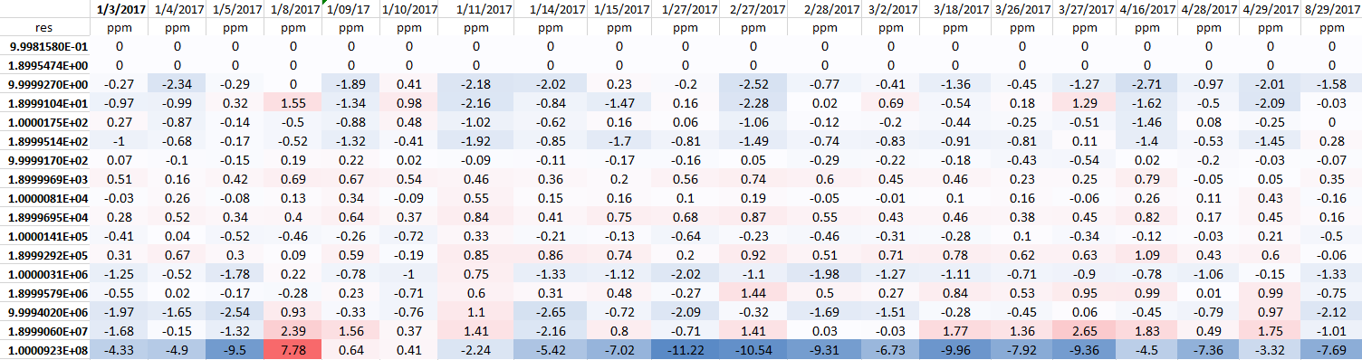
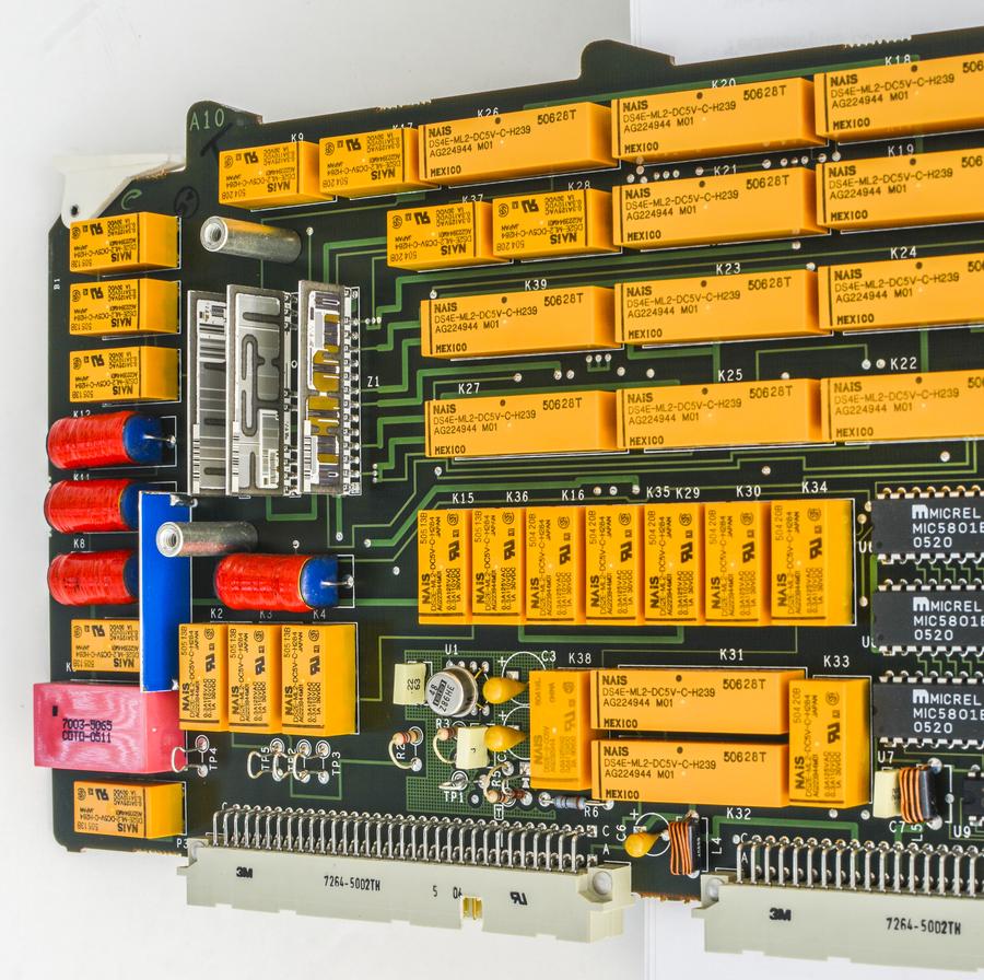
I'd say not too shabby at all for 26-year old calibrator. Ohm board was replaced at some point with one made in 2005, according to IC datecodes.

Here's how it look like, in case you forget:


Given that lab was not controlled very well, no humidity control, I'd say numbers are very nice, well under 3ppm for all resistances except 100Meg.
Major 1K, 10K, 100K resistors are better than 1ppm stable over this 8 months period.
YouTube | Metrology IRC Chat room | Let's share T&M documentation? Upload! No upload limits for firmwares, photos, files.
 

Offline Kleinstein

  • Super Contributor
  • ***
  • Posts: 14174
  • Country: de
Re: #2000 Post : Teardown and study of Fluke 5700A Calibrator [56K warning!]
« Reply #59 on: August 30, 2017, 05:06:07 pm »
For a reference / stable resistors an age of 26 or 12 years is not a problem at all. If handled proper, they get better with time. Not sure a brand new one would be that stable - unless Fluke keeps them for 1 year before delivery.
 

Offline TiNTopic starter

  • Super Contributor
  • ***
  • Posts: 4543
  • Country: ua
    • xDevs.com
Re: #2000 Post : Teardown and study of Fluke 5700A Calibrator [56K warning!]
« Reply #60 on: August 30, 2017, 05:15:43 pm »
I was more concerned of impact with all those relays. There are many in the signal path with different configuration, which all may have different contact resistance, rather than hermetical ceramic resistors themselves.  There are at least 3 relays on each resistance tap before they reach the internal MFC output bus.

Worth to note, that table above is stability versus own's 5700A "reference" 10K resistor (network Z5 on OHM CAL board), not the absolute deviation.
YouTube | Metrology IRC Chat room | Let's share T&M documentation? Upload! No upload limits for firmwares, photos, files.
 

Offline chinapp

  • Contributor
  • Posts: 33
  • Country: 00
Re: #2000 Post : Teardown and study of Fluke 5700A Calibrator [56K warning!]
« Reply #61 on: September 19, 2017, 08:33:41 am »
I think the relay should be noticed and test if the machine has been used for heavy duty,the fluke 5100 calibrator has much faults caused by  relays
http://
 

Offline Echo88

  • Frequent Contributor
  • **
  • Posts: 826
  • Country: de
Re: #2000 Post : Teardown and study of Fluke 5700A Calibrator [56K warning!]
« Reply #62 on: December 12, 2017, 02:34:56 pm »
Attached you find the ltspice-simulation (change from .txt to .asc) for the 5700A PWM-DAC, which greatly aided me in understanding the various circuit-tricks used in this schematic.

I only use Channel A PWM (V5) and added an additional R42/C12 lowpass behind the 190Hz-Filter. I didnt use this simulation since a while, but i think the rest of the component-values should be all according to the schematic.
 
The following users thanked this post: TiN, CalMachine, DC1MC

Offline Henrik_V

  • Regular Contributor
  • *
  • Posts: 156
  • Country: de
  • “ground” is a convenient fantasy
Re: #2000 Post : Teardown and study of Fluke 5700A Calibrator [56K warning!]
« Reply #63 on: December 14, 2017, 10:45:22 am »
About 5700 relays...
I was told by an old 5700 cal lab spezi  that I even if my 5700 is not in use /standby regulary do the autozero to ativate the relays, to avoid oxide between contacts.
Watching the snails,cars,....  :D
Greetings from Germany
Henrik

The number you have dialed is imaginary, please turn your phone 90° and dial again!
 

Offline bobAk

  • Contributor
  • Posts: 39
  • Country: fr
Hello. Let's revive the thread a bit. The fluke 5700a filter has about 121dB of rejection at the switched frequency. The filter input is 13 volts. At the filter output, conditionally, it should be ~ 11 microvolts. How does this fit in with his resolution? Hope for suppression by a integrator of multimeter?
 

Offline Kleinstein

  • Super Contributor
  • ***
  • Posts: 14174
  • Country: de
The 13 V would be in the 11 V FS range and peak to peak value. The RMS amplitude is smaller (e.g. a factor of 2).
The main use is with a DMM and these do offer quite some suppression of the higher frequencies, especially when using 10 PLC integration.
With a really low noise meter and short integration (e.g. 3458 with 1 PLC mode) there may be some visible residual ripple. With many other meters one would have a hard time to see it in the 10 V range.
 

Offline bobAk

  • Contributor
  • Posts: 39
  • Country: fr
Were there examples of noise measurements anywhere?  A quick search didn't help.
 

Offline branadic

  • Super Contributor
  • ***
  • Posts: 2390
  • Country: de
  • Sounds like noise
Re: #2000 Post : Teardown and study of Fluke 5700A Calibrator [56K warning!]
« Reply #67 on: December 30, 2022, 11:02:27 am »
I recently read through the following patent US11316528 PWM DAC with improved linearity and insensitivity to switch resistance that could be interesting for some of you?

Edit: Attached also the previous patent US5402082 for completeness.

-branadic-
« Last Edit: January 02, 2023, 01:59:12 pm by branadic »
Computers exist to solve problems that we wouldn't have without them. AI exists to answer questions, we wouldn't ask without it.
 
The following users thanked this post: Andreas, e61_phil, doktor pyta, guenthert, MegaVolt

Offline branadic

  • Super Contributor
  • ***
  • Posts: 2390
  • Country: de
  • Sounds like noise
Re: #2000 Post : Teardown and study of Fluke 5700A Calibrator [56K warning!]
« Reply #68 on: January 02, 2023, 02:02:33 pm »
Is there anyone out there who worked on a PWM-DAC solution and wants to share the results? What controller did you use? What INL and resolution was achieved? Does it include temperature correction? Any result or link to a project is welcome as I couldn't find much on the web.

-branadic-
Computers exist to solve problems that we wouldn't have without them. AI exists to answer questions, we wouldn't ask without it.
 

Offline Andreas

  • Super Contributor
  • ***
  • Posts: 3243
  • Country: de
Re: #2000 Post : Teardown and study of Fluke 5700A Calibrator [56K warning!]
« Reply #69 on: January 02, 2023, 02:49:35 pm »
Hello branadic,

as you already should know I used the EDN-Design

https://www.edn.com/dc-accurate-32-bit-dac-achieves-32-bit-resolution/

some results are here:

https://www.febo.com/pipermail/volt-nuts/2010-October/000537.html

The linearity shurely could be optimized if not using the whole range of the PWM.
E.g. cutting off the low and high end by adding a negative offset and amplification of the middle part.
(see last diagram here: https://www.eevblog.com/forum/metrology/stacking-ad587s-for-higher-output-voltage-(20v-30v-etc-)/msg1320513/#msg1320513 )

Alternatively one could do a mathematical correction. (of both linearity + temperature)
As controller any controller can be used which has at least 3 synchronizable 16 Bit PWM outputs which should be a multiple of the AC mains frequency to use the NMR of a multimeter. (e.g. 244 Hz or 300 Hz PWM frequency)

As controller I tested ATMega1284, PIC24FV32KA302 and one DSPIC.

with best regards

Andreas

 
The following users thanked this post: deepfryed, MegaVolt

Offline branadic

  • Super Contributor
  • ***
  • Posts: 2390
  • Country: de
  • Sounds like noise
Re: #2000 Post : Teardown and study of Fluke 5700A Calibrator [56K warning!]
« Reply #70 on: January 02, 2023, 06:18:54 pm »
Hi Andreas,

yes I know and was at some point working on a PCB as you might remember.
Unfortunately, the design only supports a 5 V reference and output but not (±)10 V, which is sad now that we have ADR1399, LTZ1000 and ADR1000.
Also the discussion about it such as the poor INL didn't convience me yet to make progress on the board.  :palm:

-branadic-
Computers exist to solve problems that we wouldn't have without them. AI exists to answer questions, we wouldn't ask without it.
 

Offline DavidKo

  • Frequent Contributor
  • **
  • Posts: 295
  • Country: cz
Re: #2000 Post : Teardown and study of Fluke 5700A Calibrator [56K warning!]
« Reply #71 on: January 03, 2023, 03:07:05 pm »
branadic: I had started to look how to improve the PWM-DAC used in 10MHz GPSDO. I have found 2 very similar solutions (2x 8bit PWM summed together) https://www.edn.com/combine-two-8-bit-outputs-to-make-one-16-bit-dac/ and https://www.ti.com/lit/an/sboa379/sboa379.pdf?ts=1651209621298.
edit: TI designed DAC is in https://www.ti.com/lit/an/slyt795/slyt795.pdf


During my investigation I have found some remark about PWM DAC with 8051 used for some space programm (I think that they have generated AC signal), Keithleys 38x SMUs, Advantest R6144. It seems that it is used all around us as a common way to change voltage or generate AC signal. Quite solid as can be seen on Keithley or Advantest examples. In theory one can combine 2 16 bit DACs to create 32bit signal. But it seems to me that DAC used in GPSDO cannot be simply build on the breadboard (voltage in my GPSDO is not too much stable).

« Last Edit: January 03, 2023, 03:38:29 pm by DavidKo »
 

Offline guenthert

  • Frequent Contributor
  • **
  • Posts: 712
  • Country: de
Re: #2000 Post : Teardown and study of Fluke 5700A Calibrator [56K warning!]
« Reply #72 on: January 03, 2023, 06:17:42 pm »
branadic: I had started to look how to improve the PWM-DAC used in 10MHz GPSDO.
[..]
Correct me if I'm wrong, but a PWM DAC in a GPSDO doesn't need to be particular linear (it doesn't even have to be monotone) as it is used in the control loop (it's errors are just another error source auto-compensated, 'disciplined').  I don't think it needs to be very stable either.

DAC used in GPSDO cannot be simply build on the breadboard (voltage in my GPSDO is not too much stable).
All long time drift will be auto-compensated by the GPS' PPS signal averaged over time.  Of concern methinks (but I admit, I haven't thought this through :-[) is only short term drift, noise.  Perhaps you'd be better off with a PDM DAC instead of PWM, as the former is easier to filter.
 

Offline guenthert

  • Frequent Contributor
  • **
  • Posts: 712
  • Country: de
Re: #2000 Post : Teardown and study of Fluke 5700A Calibrator [56K warning!]
« Reply #73 on: January 03, 2023, 06:25:02 pm »
I recently read through the following patent US11316528 PWM DAC with improved linearity and insensitivity to switch resistance that could be interesting for some of you?

Edit: Attached also the previous patent US5402082 for completeness.

-branadic-

Thanks, but that patent looks like it has been written by a robot, not a lawyer.  Skimming over it, it looks like Fluke prevents anyone else to use PWM with two switching networks without actually explaining how this addresses errors of (varying) switch resistance, imperfect, varying switch timing, stray capacities in the switches and charge injection.  But then, perhaps it is obvious to those skilled in the art.  Did anyone grok it and can translate it here to English, pretty please?
 

Offline DavidKo

  • Frequent Contributor
  • **
  • Posts: 295
  • Country: cz
Re: #2000 Post : Teardown and study of Fluke 5700A Calibrator [56K warning!]
« Reply #74 on: January 03, 2023, 06:58:43 pm »
...
Correct me if I'm wrong, but a PWM DAC in a GPSDO doesn't need to be particular linear (it doesn't even have to be monotone) as it is used in the control loop (it's errors are just another error source auto-compensated, 'disciplined').  I don't think it needs to be very stable either.
...
All long time drift will be auto-compensated by the GPS' PPS signal averaged over time.  Of concern methinks (but I admit, I haven't thought this through :-[) is only short term drift, noise.  Perhaps you'd be better off with a PDM DAC instead of PWM, as the former is easier to filter.

You need short therm stability. It is not possible to measure the tuning voltage after filtering. It goes up and down ~50 mV in 1 second.

Second reason is that I want to use 12V oscillator and the PWM DAC from CMOS inverter (I know that I can use one buffer and big capacitor, but why not to build it with feedback).
« Last Edit: January 03, 2023, 07:16:16 pm by DavidKo »


Share me

Digg  Facebook  SlashDot  Delicious  Technorati  Twitter  Google  Yahoo
Smf