Not very long ago I've started hobbyist
first thread about Fluke 5700A series calibrator. It's time to continue this sick practice to tear apart expensive metrology equipment, don't you agree? Calibrator in that thread living well since the overhaul last year and was used to calibrate number of 3458A's, few Datron 1281's and even my second 3458A back in January'17.
With access to 732A/B and 1ohm/10K SR104 resistance standards it's not hard to calibrate 5700A to it's 24hr spec. But how about AC voltage and current calibration? Calibration manual calls out for Fluke 792A AC/DC transfer box. Well, some patient hunting and here we go now..
 Intro
IntroThe Fluke 792A is an very high accuracy AC/DC Thermal Transfer Standard, designed to meet the most demanding ac traceability requirements. Using the patented Fluke RMS sensor and thin film range resistors, the 792A offers an extraordinary transfer accuracy, with total uncertainties of as low as ±10 ppm (±5 ppm from the NIST). The 792A also provides a wide voltage range of 2 mV to 220V (1000V with external range resistor), and a wide frequency range of 10 Hz to 1 MHz.
The Fluke solid-state RMS sensor also provides the 792A with remarkable temperature stability and fast settling time. Now you can be ready to make measurements in 30 seconds instead of 30 minutes. To simplify the transfer process, the 792A's 2V output permits you to use a high resolution digital multi meter rather than a null meter. The Fluke 792A is designed to support the calibration of the most accurate ac instruments in your standards lab workload, including calibrators like the Fluke 5700A, voltmeters like the Fluke 8506A, voltage amplifiers and other ac/dc transfer standards
Fluke 792A is main standard used to test and characterize multifunction calibrators, such as
Fluke 5700A/5720A/5730A and AC voltage measurement standards, such as Fluke 5790A, Fluke 5790B and
Wavetek 4920.
Manuals and documentationFluke 792A Instruction manualExterior and user interface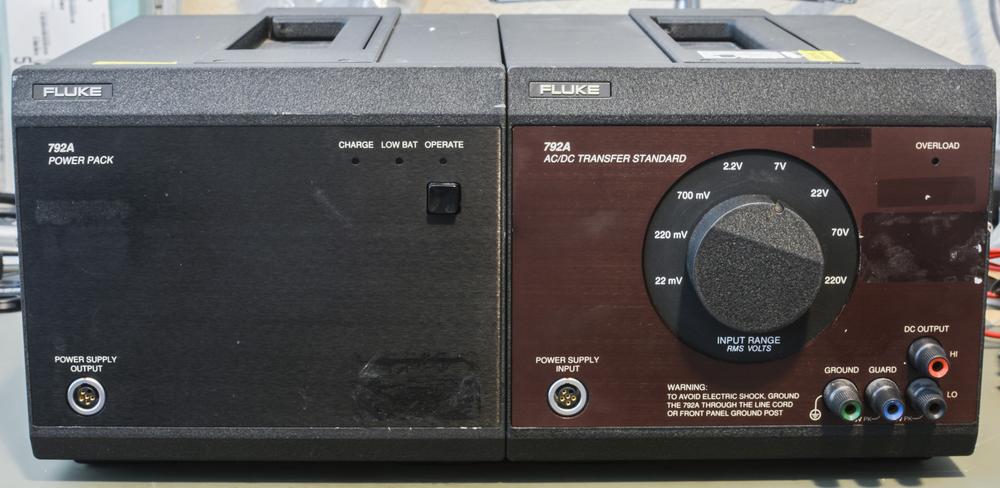
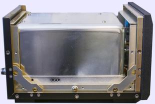
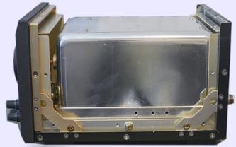
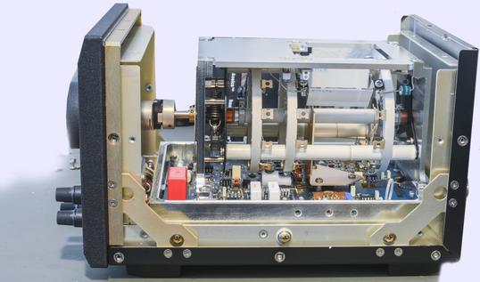
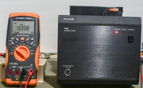
Standard consists of two boxes, one being battery block/power supply (on the left) and actual transfer standard (on the right). If you buy it from Fluke for serious amount of money, you also get fancy transfer switch to toggle input connection for standard and external 1000V range resistor, to measure high voltages. Transfer box itself can only measure up to 220VAC/VDC. In this ebay deal we got no 1000V range resistor, so will to hunt that rare beast separately...
Teardown and design evaluationWell, like we say it here, "Don't turn it on, take it APAAAAART!"

. Let's start.
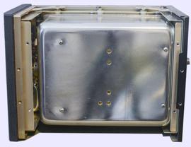
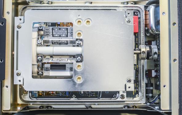
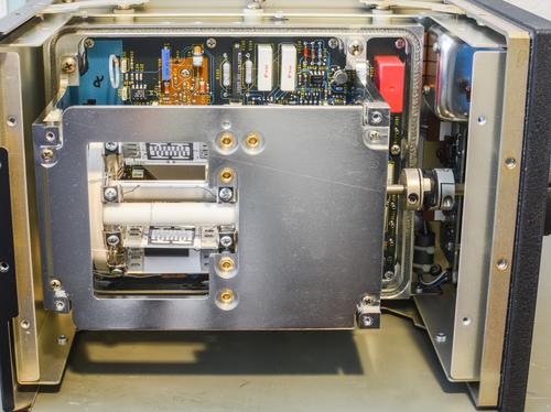
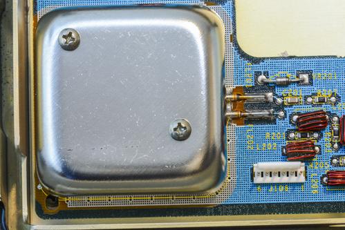
Shield under the shield under the shield. Like those Matreyska dolls of metrology

Don't breathe...
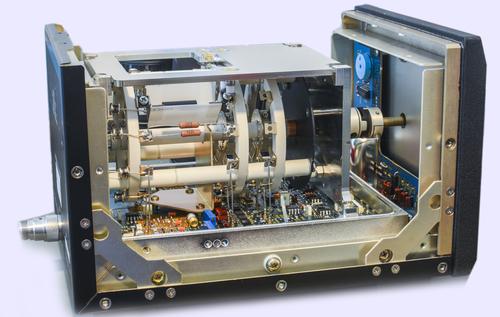
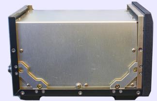
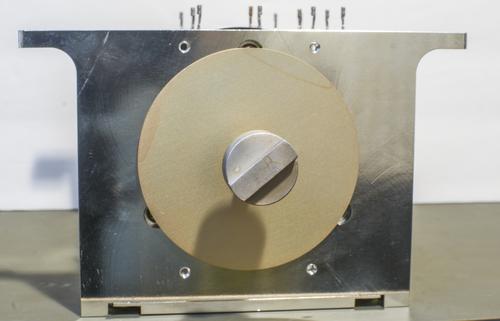
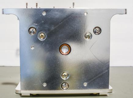
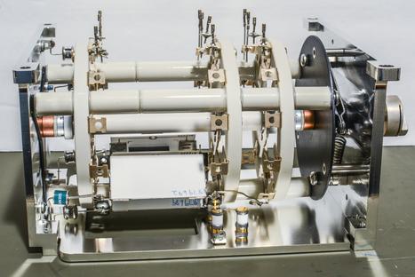
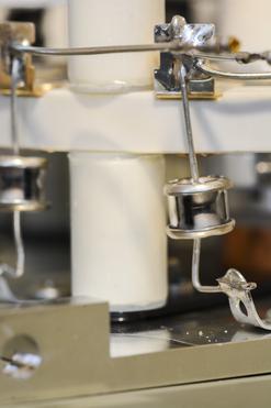
Look at the construction. Wonder how many engineering hours was spend on just chassis alone.
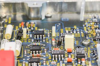
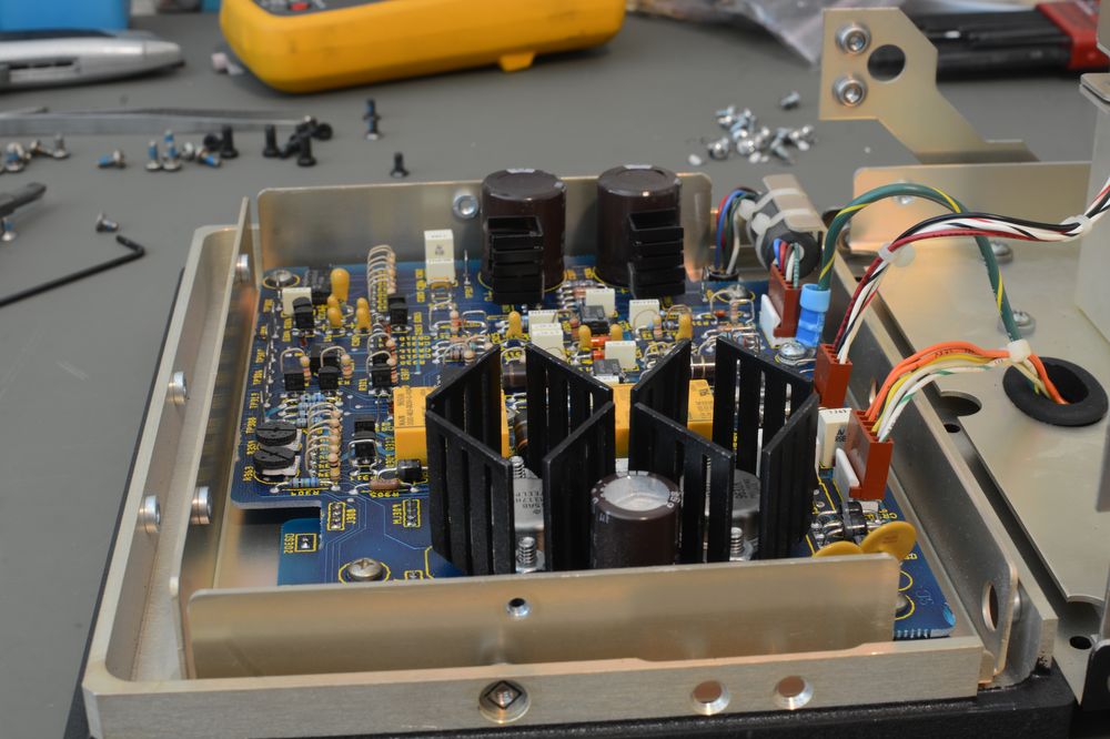
Some componentry around:
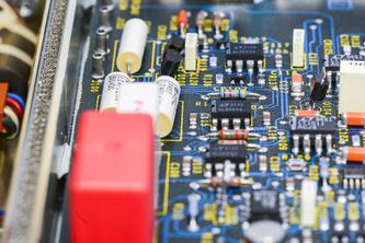
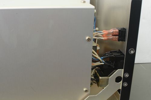
Attention to details, zip-tie hooks to get board out if required. Steel wool in the chamfered corner to ensure good RF contact with shield box, to make sure no electrons escape!
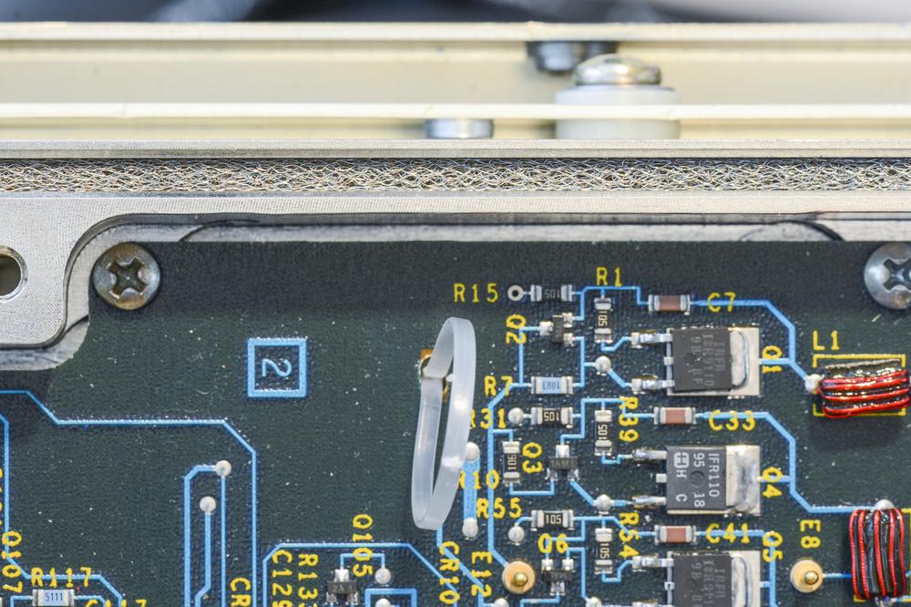
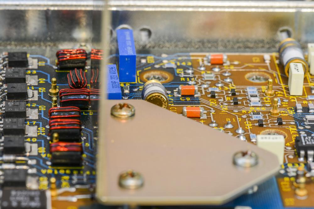
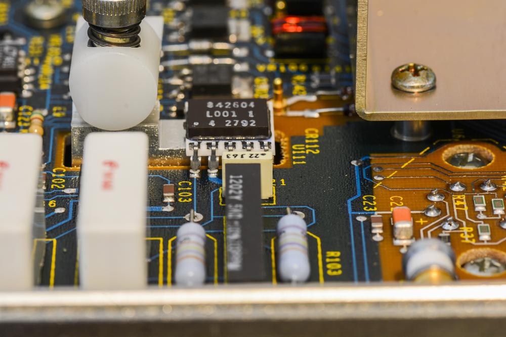
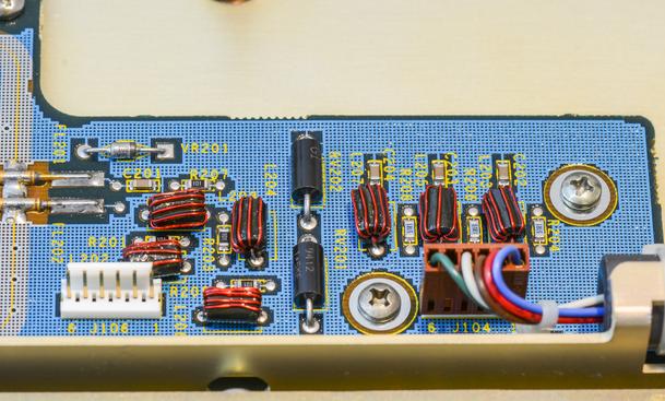
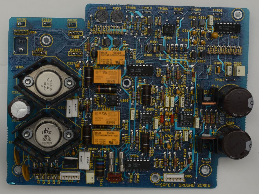
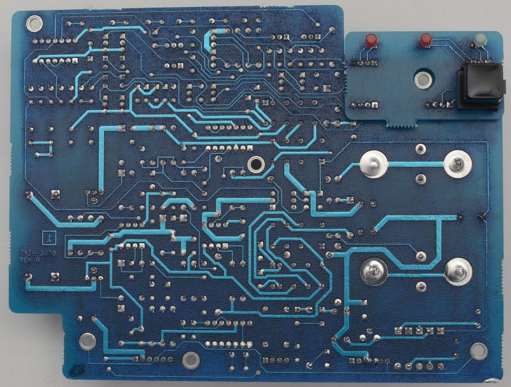
Some of the areas of PCB are exposed of soldermask, to have more stable frequency response over the tracks.
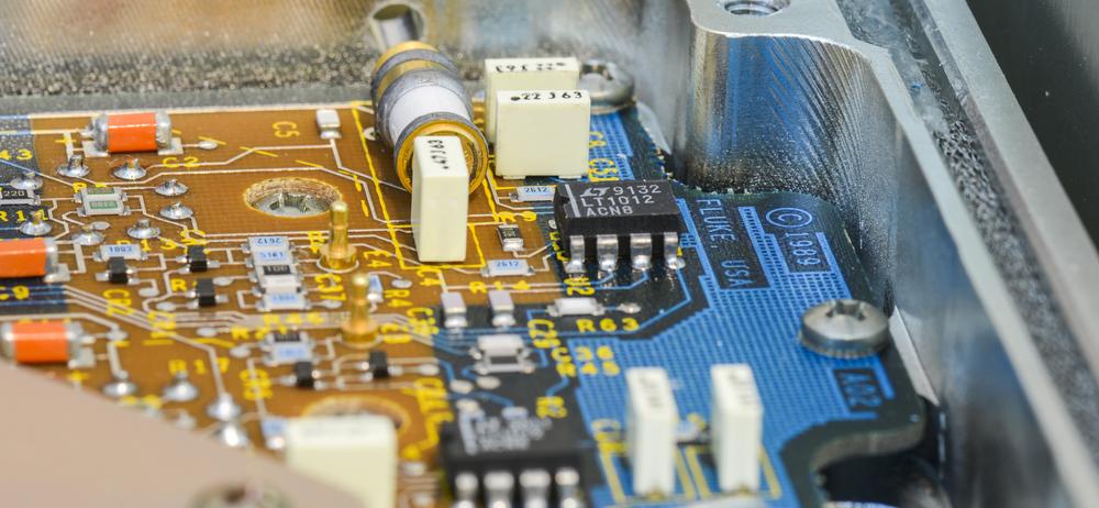
Plenty of filtering and LC circuits for power.
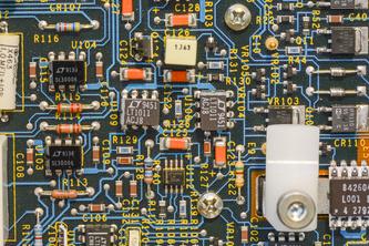
According to date codes on components, this specific 792A was manufactured in the middle of 1996, some 20 years ago.
Range switch assemblyTo maintain specification and long term stability, Fluke 792A RMS sensor and hermetic range resistors contain Beryllium Oxide ceramics. While normal use of 792A is safe, BeO dust or fumes from damage to these components HIGHLY TOXIC and breathing them can result in serious injury or worse. Beryllium is IARC Group 1/EPA Class A EPA carcinogen and exposure can cause Chronic Beryllium Disease, an often fatal lung disease. Never disassemble, grind, lap, fire or chemically clean on any ceramic parts inside 792A.
We don't plan any of that, phew...
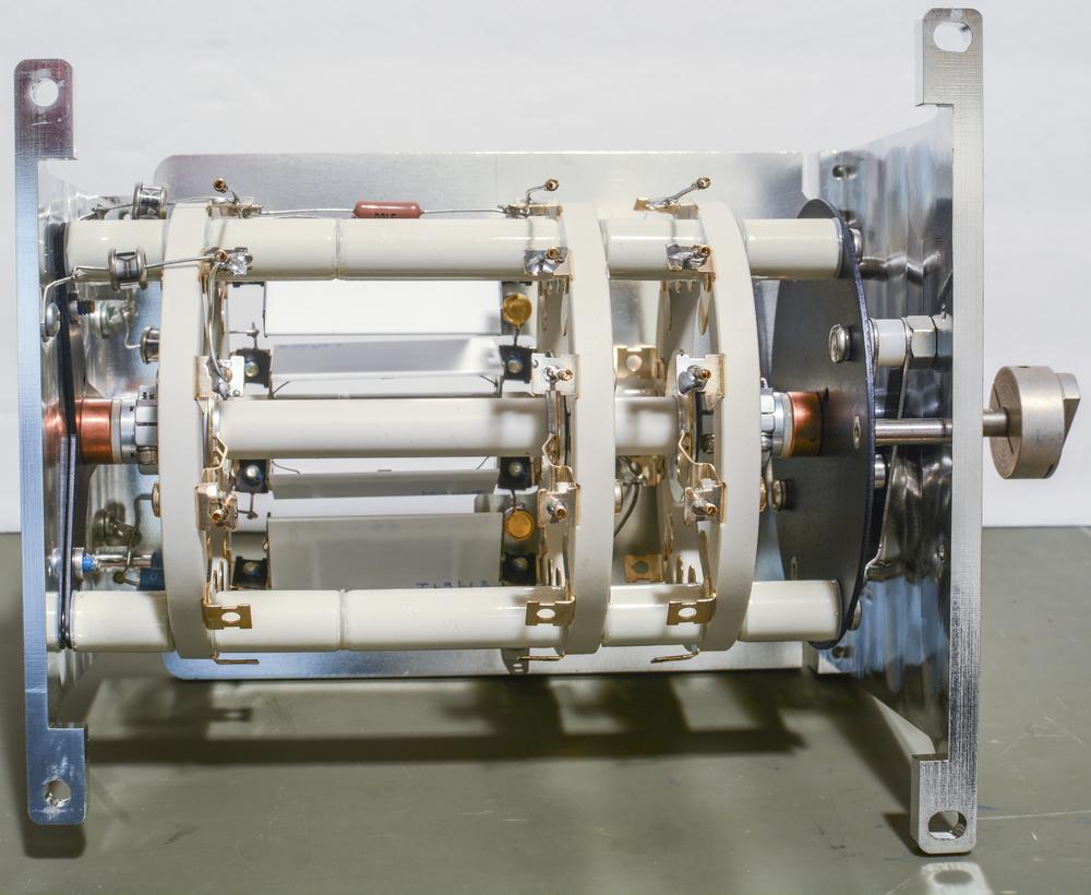
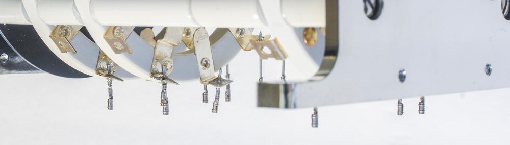
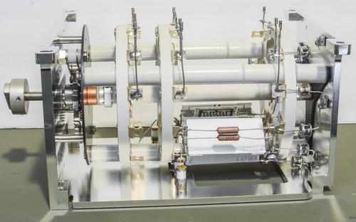
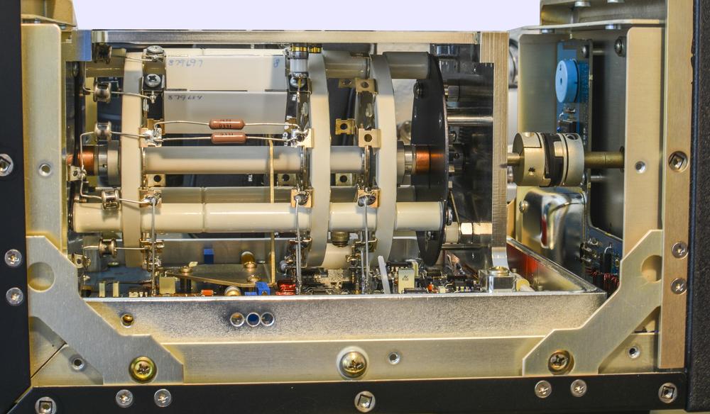
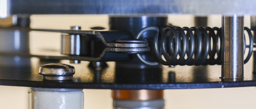
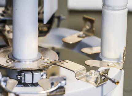
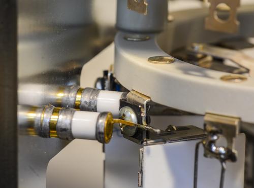
Isn't this most beautiful range switch assembly you ever saw?
There is even spot for few PTF's
Bit of wiper action:

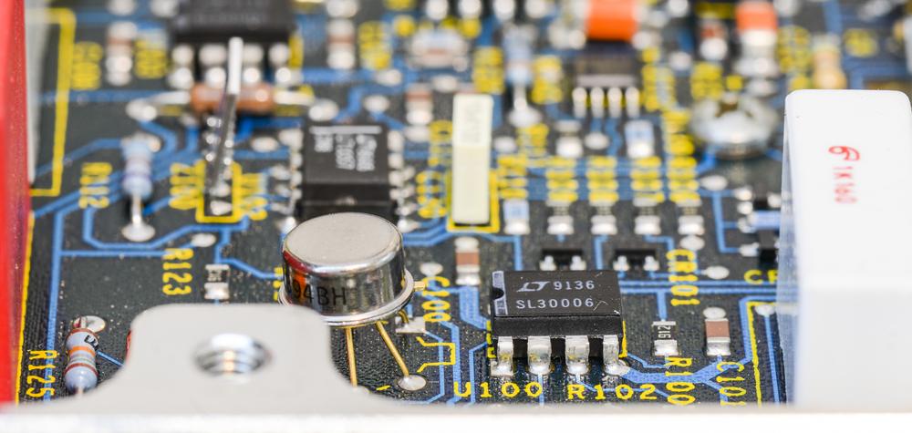
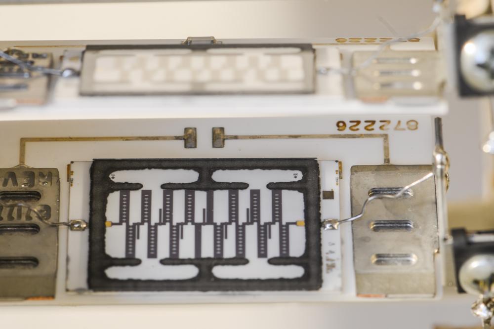
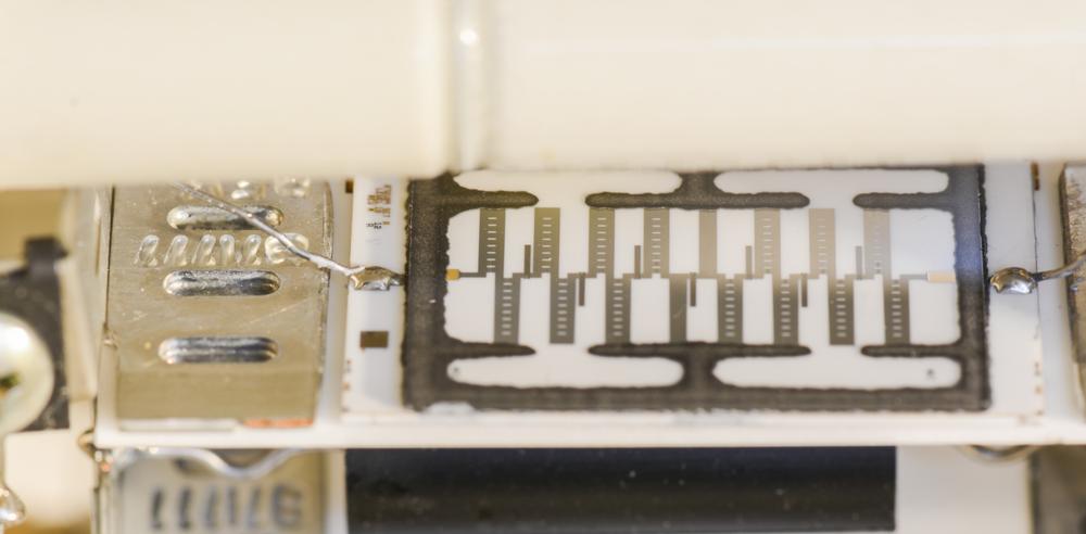
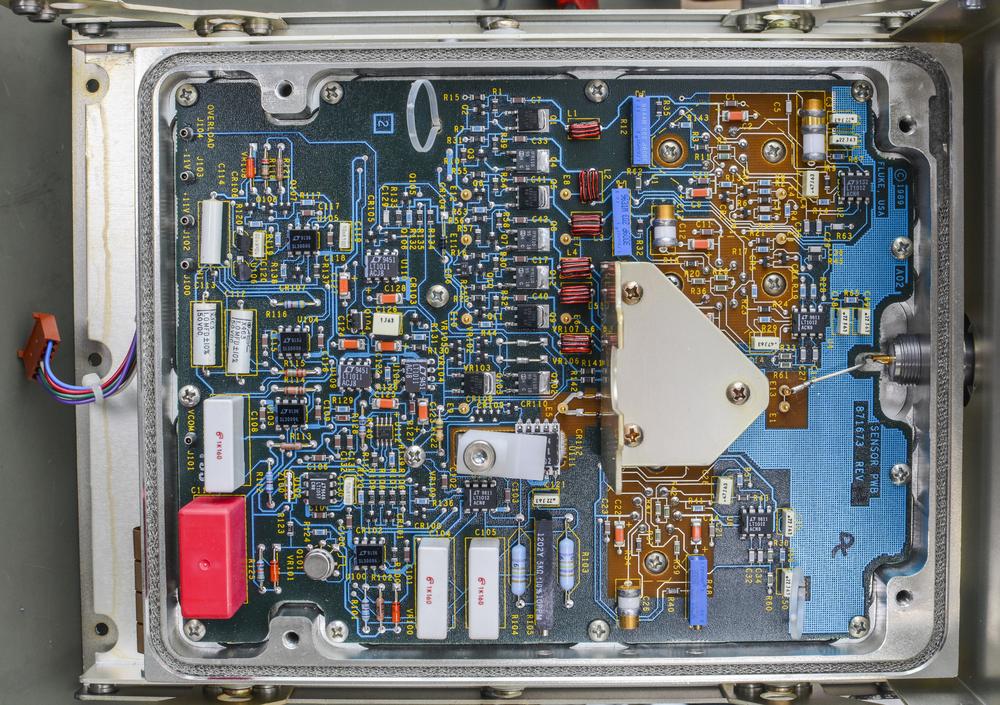
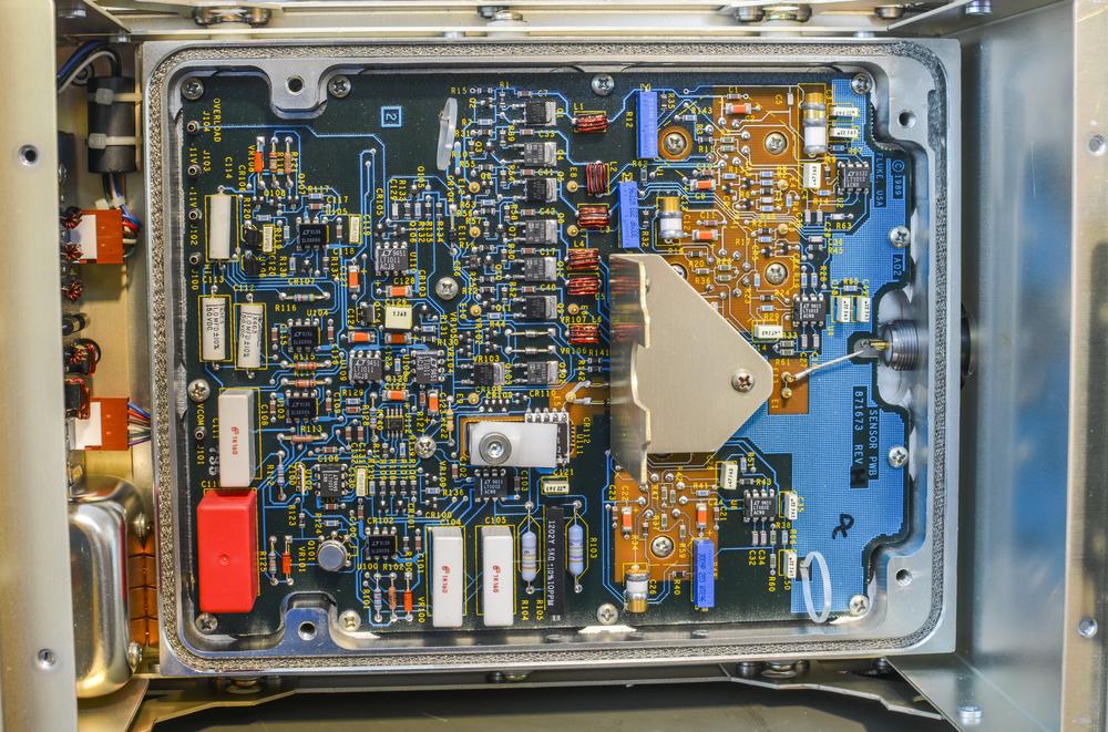
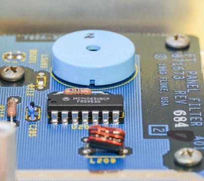
 Sensor PCBA
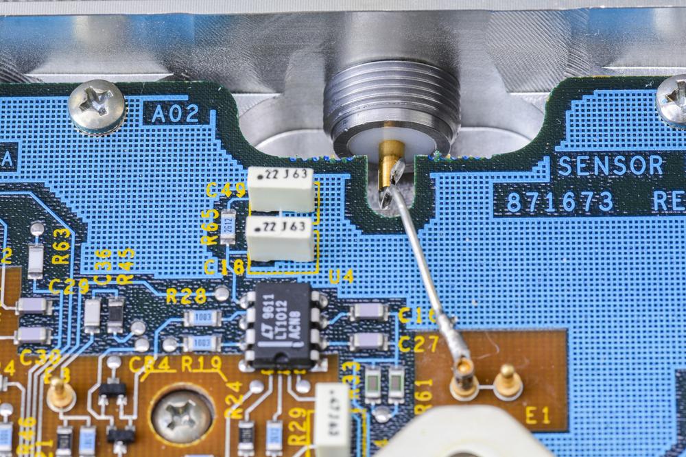
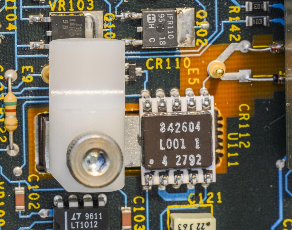
Core of the instrument, Fluke's thermal solid state sensor hybrid:
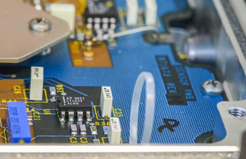
And few overview shots:
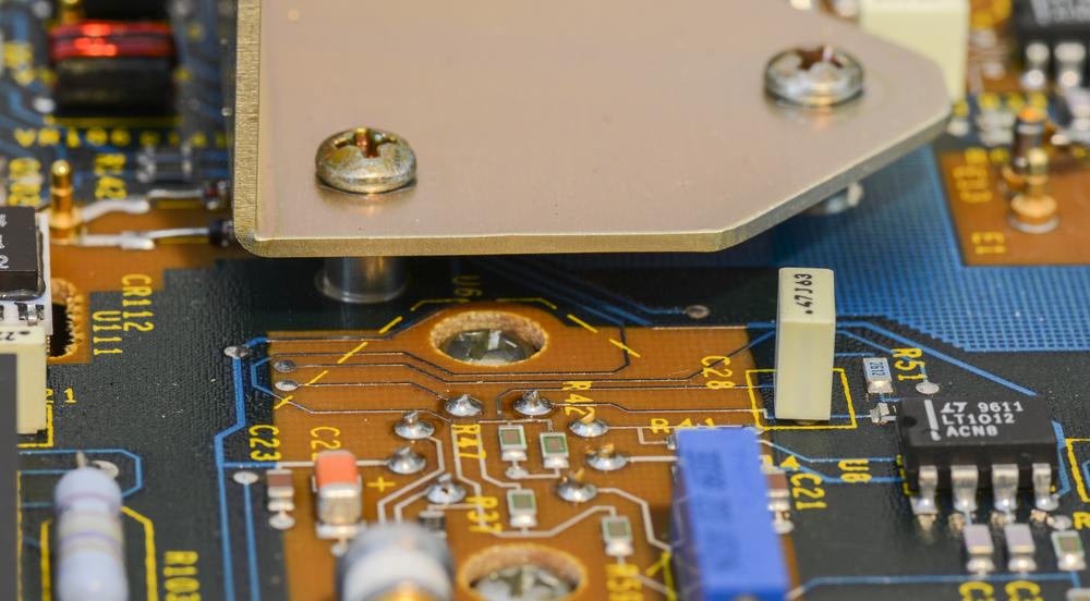
 Sensor test
The key component of Fluke 792A performance is custom solid-state thermal transfer RMS sensor. It's not impossible that this RMS sensor is failed, and that can quickly make unit's complete repair very expensive.
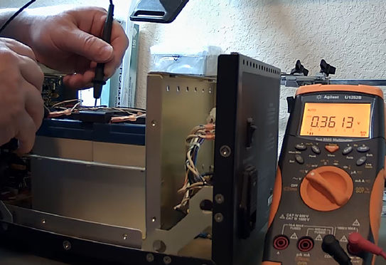
So one of reasons why we get everything apart to this level, is to actually check if RMS sensor good or not. Procedure of this simple test listed in instruction manual in troubleshooting section. It calls to measure resistance between pins 6 and 7 of U111 sensor hybrid assembly. If it's no longer between 368 Ω and 432 Ω then U111 sensor is damaged and must be replaced.
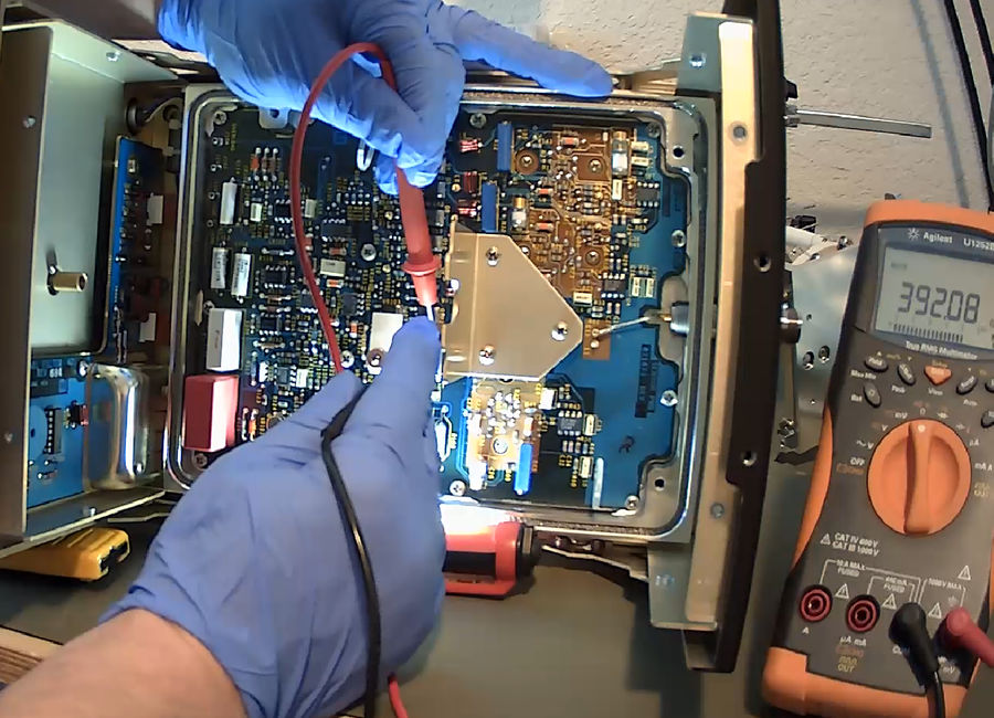
Our measurements with portable Agilent DMM shown sensor resistance 392 Ohm, very well within expected good range. Big "Phew!" moment here!
Front filter PCB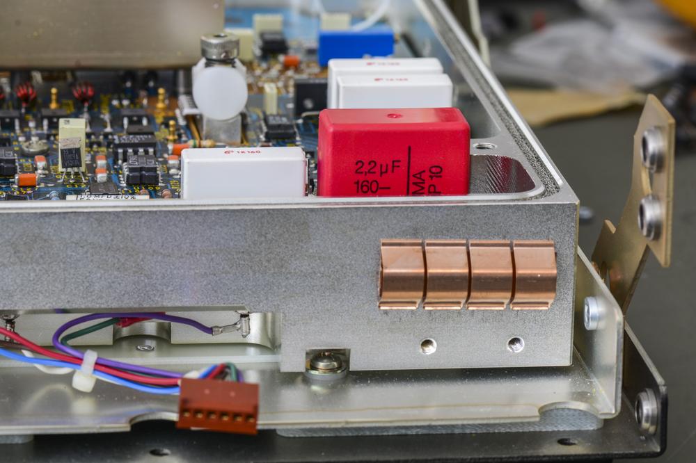
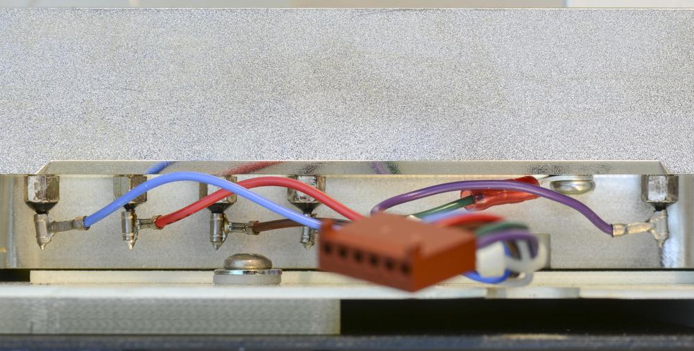
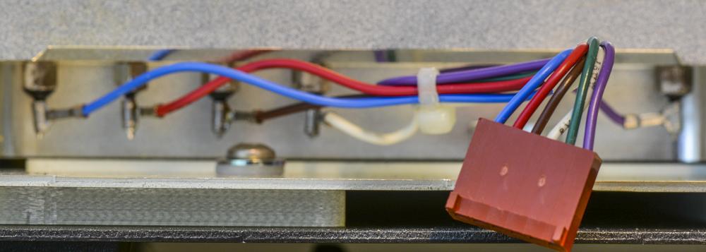
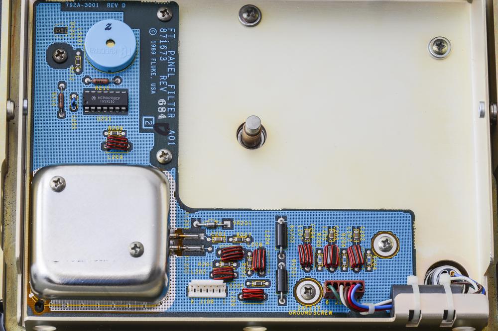
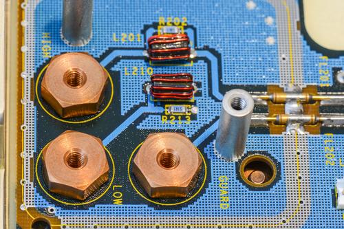
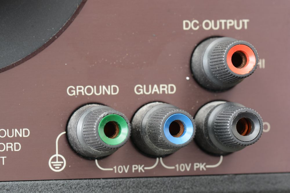
Standard DC output, guard and ground terminals are connected to high quality copper 5-way binding posts, very similar to ones used in Fluke 57xx series calibrators and other Fluke standards. Similar connectors can be bought from
Low Thermal for about $25/piece.
 Troubleshooting and repair
Before we test transfer box, need to fix PSU first.
Model 792A Power pack repairIn condition as received power pack does not show any signs of life, and does not turn on with AC power. Simple check procedure hinted from instruction manual.
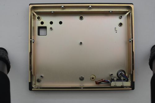
Initial cover removal only shows more shields inside. Fluke 792A build like a famous Matreska dolls, box inside a box inside a box.
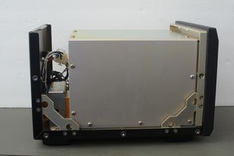
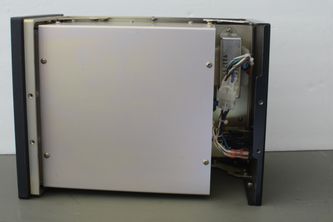
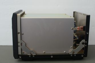
Shielded box in center contain four 6V sealed batteries, which are likely dead after 20 years. Let's see.
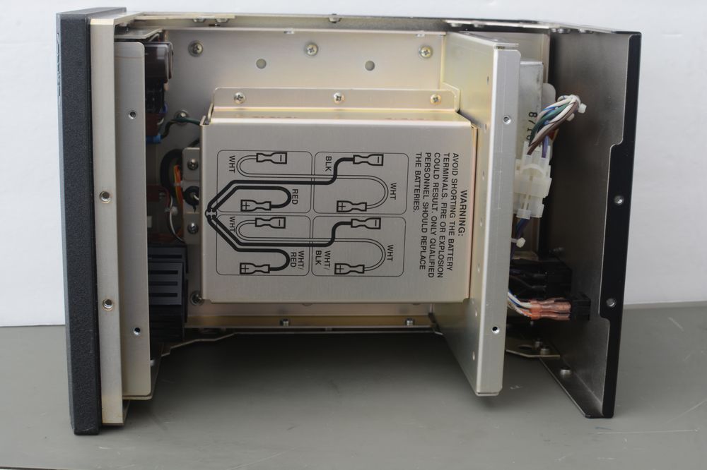
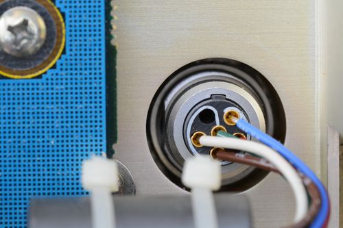
This can be done either by measuring battery pack output at J303 connector (should measure around 12V pin 1-2 and 12V pin 3-4). Or simply remove the cover and just to check each battery terminal voltages.
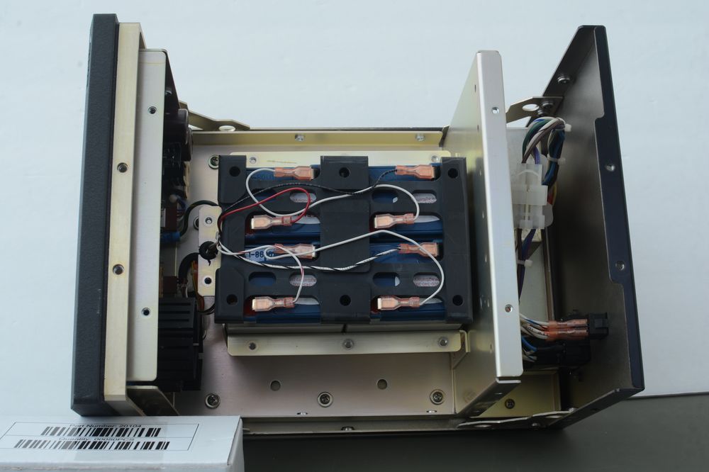
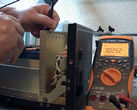
Well, no comments required, all four batteries are completely dead. Let's remove then and get access to power supply PCBA. This is done by removing front chassis side.
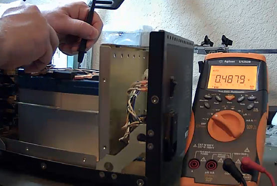
After temporary change with two good 12V battery, output voltage was measured at expected +/-11.3 V levels. However relay K30x which connect charger to the battery got very hot quick. Powering unit with AC made relays click very fast for a second and that was it.
At least we know at this point that output voltage regulator is correctly working, which bring some confidence that even if transfer 792A unit have problem, it's not came from power supply. So focus on troubleshooting now is on charge/detection circuitry. Fluke supplies schematics of 792A to our benefit (Thank you, Fluke!) so that makes troubleshooting bit easier.
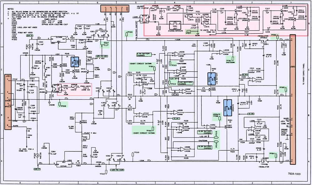
Both negative and positive regulators are symmetrical, and can be used to compare each side for faster troubleshooting.
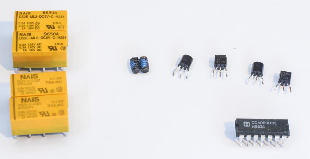
After investigation and few days of troubleshooting, next parts were replaced. Relays were replaced just in case.
* Make sure fuses F301, F302 are OK. Voltage difference between fuse terminals should equal zero.
OK..* Measure supply voltage on U307 at pins 14-7. Should be around ~12VDC.
OK..* If OPERATE indicators briefly goes on at power on, there is likely a short. Check resistance between test points TP302 (+11V), TP304 (-11V) and TP305 (Common). Automatic shutdown also activated in case of too low battery voltage (can be checked at J303 connector).
OK..* If battery charger is faulty, check mains fuse and voltage setting.
OK..* Use scope to measure U301 pin 2 and pin 3 with respect to TP308 (Charger COMMON). Should see half-sine waves about 24V[~pk-pk~].
OK..* Logic supply voltage should be around +22VDC between cathode of CR309 and TP308 test point.
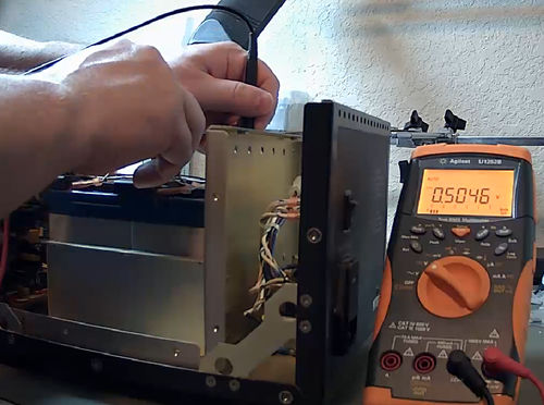
OK..As a result, Power pack block now working as expected. Larger batteries were used for test, while replacement already on their way.
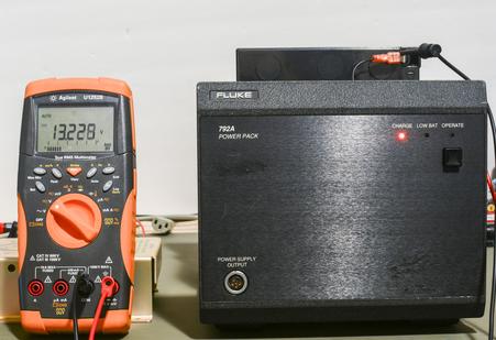
Both BT1 and BT2 battery now charging as expected, reaching ~13.2 and ~13.3 VDC after 16+ hours of charge.
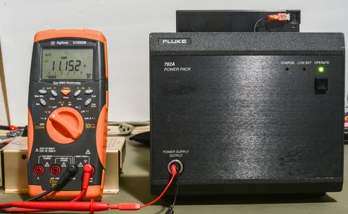
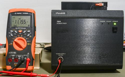
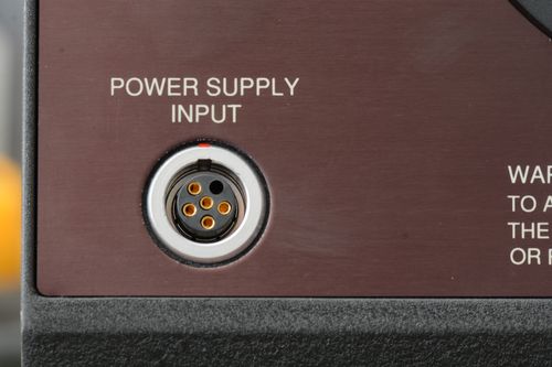
Output voltages are within few millivolts positive and negative, well in spec. Now order some LEMO connectors, make a cable (straight 1:1 coonection, no worry) and we are ready.
Initial testsInput of 792A has an internal protection circuitry that guards against accidental overvoltage. However, the instrument may be damaged if the PSU turned on while voltage is applied to the Type-N input connector. Always turn the power switch ON BEFORE applying a signal to the input connector.All range resistors were checked good, so time to connect 792A to Fluke 5700A, some random 3458A laying around and see some transfers.
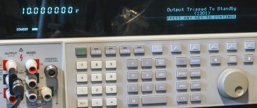
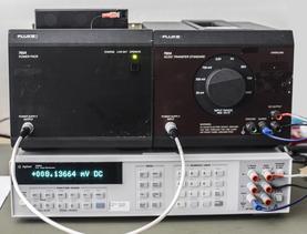
2.2VAC 1kHz applied to 792A input (left) and 2.2VDC applied to 792A input (right)
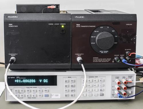
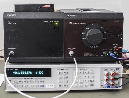
It works, yay!
As usual full worklog is maintained and updated
on xDevs.com site.


