Author Topic: Characterization and measurements for low-resistance shunts?  (Read 5924 times)

0 Members and 1 Guest are viewing this topic.

Offline TiNTopic starter

  • Super Contributor
  • ***
  • Posts: 4543
  • Country: ua
    • xDevs.com
Characterization and measurements for low-resistance shunts?
« on: February 05, 2017, 03:59:05 pm »
It's time somebody with more metrology knowledge to shed some light on me. As a result of mixed test data from shunts replacement in my test DMM, I tried to test other low-resistance (<10 ohm) shunts in one aspect - temperature coefficient. But latest data left me with more questions than answers.

Test device: 4-wire 20 mOhm Vishay PG VCS101 shunt. It's specified to have 30ppm TCR.
Test setup: Nanovoltmeter Keithley 182-M + calibrator TE 9823 as current source.

Now I sourced 100mADC to shunt, connected separate sense cable from shunt to nV-meter and measured resulting voltage drop over temperature span 20K. Resistance was calculated by simple R = V/I. I had current running thru 3458A and can confirm current was stable within 20ppm over all time of test. Orange line is temperature in the box, blue line is calculated shunt resistance.


Now, resulting tempco calculated at +617ppm/K which makes this shunt more like thermistor, rather than precision shunt. Then I thought, maybe it's self-heating from 100mA test current cause this result?

Retest with 10mA current, everything else is exactly same, did not even take resistor out of the temperature box.


7551 ppm/K, more than 10 times worse result.

Retest once more with 1000mA current over the same shunt:


+76 ppm/K. Still way above specified 30 ppm.

Does this mean that shunts need to be tested at their nominal currents (which would be around 8A for specified power) to obtain specified tempco? Or am I missing something important here and shunts below 1 ohm measured differently?  :-DMM
« Last Edit: February 05, 2017, 04:02:34 pm by TiN »
YouTube | Metrology IRC Chat room | Let's share T&M documentation? Upload! No upload limits for firmwares, photos, files.
 

Offline rx8pilot

  • Super Contributor
  • ***
  • Posts: 3634
  • Country: us
  • If you want more money, be more valuable.
Re: Characterization and measurements for low-resistance shunts?
« Reply #1 on: February 05, 2017, 04:05:57 pm »
This is interesting....

Curious what current source are you using, thermal chamber, etc. It would be nice to have a sense of the test configuration and environment.

Sent from my horrible mobile....

Factory400 - the worlds smallest factory. https://www.youtube.com/c/Factory400
 

Offline rx8pilot

  • Super Contributor
  • ***
  • Posts: 3634
  • Country: us
  • If you want more money, be more valuable.
Re: Characterization and measurements for low-resistance shunts?
« Reply #2 on: February 05, 2017, 04:07:26 pm »
This is interesting....

Curious what current source are you using, thermal chamber, etc. It would be nice to have a sense of the test configuration and environment.

Sent from my horrible mobile....
Never mind on current source.....

Sent from my horrible mobile....

Factory400 - the worlds smallest factory. https://www.youtube.com/c/Factory400
 

Offline CalMachine

  • Frequent Contributor
  • **
  • Posts: 477
  • Country: us
  • Metrology Nut
Re: Characterization and measurements for low-resistance shunts?
« Reply #3 on: February 05, 2017, 04:31:44 pm »
I know with Empro current shunts, you definitely need to test them closer to their rated current.  I would have said 25% is probably the very minimum you should go, and your results show a similar story.  For as small of a package as those Vishay shunts are, I'm surprised they don't perform better for far lower current than its rating.  I'm also surprised Vishay doesn't have anything about that in their datasheet.
All your volts are belong to me
 

Offline Alex Nikitin

  • Super Contributor
  • ***
  • Posts: 1165
  • Country: gb
  • Femtoampnut and Tapehead.
    • A.N.T. Audio
Re: Characterization and measurements for low-resistance shunts?
« Reply #4 on: February 05, 2017, 04:37:42 pm »
It looks like you are measuring a thermocouple voltage somewhere in your setup. You reduce the current 10 times and that TC voltage becomes 10 times more noticeable relative to the measured voltage on the shunt. You increase current and the TC voltage influence is reduced proportionally.

Cheers

Alex
 
The following users thanked this post: TiN

Offline TiNTopic starter

  • Super Contributor
  • ***
  • Posts: 4543
  • Country: ua
    • xDevs.com
Re: Characterization and measurements for low-resistance shunts?
« Reply #5 on: February 05, 2017, 04:38:49 pm »
Thermal box is same I used for TC testing on LTZ module. Its design and photos described here.
YouTube | Metrology IRC Chat room | Let's share T&M documentation? Upload! No upload limits for firmwares, photos, files.
 
The following users thanked this post: rx8pilot

Offline Alex Nikitin

  • Super Contributor
  • ***
  • Posts: 1165
  • Country: gb
  • Femtoampnut and Tapehead.
    • A.N.T. Audio
Re: Characterization and measurements for low-resistance shunts?
« Reply #6 on: February 05, 2017, 04:42:56 pm »
As a simple test - change the polarity of the current.

Cheers

Alex
 

Offline CalMachine

  • Frequent Contributor
  • **
  • Posts: 477
  • Country: us
  • Metrology Nut
Re: Characterization and measurements for low-resistance shunts?
« Reply #7 on: February 05, 2017, 04:45:15 pm »
It looks like you are measuring a thermocouple voltage somewhere in your setup. You reduce the current 10 times and that TC voltage becomes 10 times more noticeable relative to the measured voltage on the shunt. You increase current and the TC voltage influence is reduced proportionally.

Cheers

Alex

If that's the case.  Couldn't one can set the source to 0 mADC, if possible, let everything settle.  Rel/Null meters.  Set source back to nominal.  and you would have to do this for each nominal temperature value?
All your volts are belong to me
 

Offline David Hess

  • Super Contributor
  • ***
  • Posts: 16607
  • Country: us
  • DavidH
Re: Characterization and measurements for low-resistance shunts?
« Reply #8 on: February 05, 2017, 05:36:03 pm »
It looks like you are measuring a thermocouple voltage somewhere in your setup. You reduce the current 10 times and that TC voltage becomes 10 times more noticeable relative to the measured voltage on the shunt. You increase current and the TC voltage influence is reduced proportionally.

I suspect thermocouple effects also.  The construction of a low temperature coefficient current shunt is not going to be low thermocouple effect friendly with the resistance element itself, the leads or terminations, and the connections to the terminations.  100mA through 20mOhms is only 2mV.

As a simple test - change the polarity of the current.

Or use AC excitation and make an AC measurement.

On the other hand, this demonstrates the limit of using a current shunt at low DC voltage drop.
 

Offline Vgkid

  • Super Contributor
  • ***
  • Posts: 2710
  • Country: us
Re: Characterization and measurements for low-resistance shunts?
« Reply #9 on: February 05, 2017, 08:53:30 pm »
As others have noticed the thermocouple effect is playing into your measurements. Often times standard resistors were run with currents  to generate potential voltages as high as 100mv. In an strictly dc measurement(not pulsed) one can even note the values of resistance become unstable. When I was running the old school ratiometric switch contact resistance test(I think in the 4232 thread) after several seconds the readings become unstable on the microvolt level(we have a max of 1mv applied applied to the switch).
« Last Edit: February 06, 2017, 04:16:49 am by Vgkid »
If you own any North Hills Electronics gear, message me. L&N Fan
 

Offline MisterDiodes

  • Frequent Contributor
  • **
  • Posts: 457
  • Country: us
Re: Characterization and measurements for low-resistance shunts?
« Reply #10 on: February 05, 2017, 09:26:44 pm »
TiN -  Just some thoughts:

Yes, watch out for thermocouple effects here.  For low ohm's current shunt use AC or use a switch gear setup, and keep flipping the current flow thru the DUT for best results.

Normally for low-ohms shunts you measure at about the mid-range of rated current for best TC.  Measuring at very low currents may not be useful.  Better yet you measure the TC at the typical and max current as required by the application, when it's mounted in its final location - that will get you the most "real" results.  Testing a shunt's TC out of circuit may or may not be very useful.

Also head's up:  At low ohms those copper leads will have a surprising Delta-R effect also.

If I remember right - and you will want to check this with Vishay apps engineering - but these datasheets seem to focus on the TC of the resistive element itself.  I think somewhere they have another datasheet on the TC / Resistive effects of the terminations of the leads.  That -might- apply here, I haven't looked.

This datasheet doesn't list the lead effects directly, so that leads me to believe they might have left it off - but remember at low ohms every but any length of copper will have an effect on heating, power dissipation, etc.

DON'T FORGET - At low ohms, even though you have 4 wire sensing, you still have to take into account the PC board trace heating as well...  That's going to affect your overall apparent TC and response times on these things also.   The faster the current changes the faster the foil dimension changes, which can happen faster than the substrate can move - and if this happens rapidly you will get a Del-R or the stress between the foil and the substrate.

Heat flow is -everything- with these so that's why we usually wait until the current shunt is mounted on a real PCB and inside a real enclosure before trying to make any accurate TC measures.  That might apply here also, depending on what you're building.

I suggest you build up a section of PCB that resembles your application heat flow, make sure you're not using straight DC, and get that excitation current flow up to where about where you need it to be most accurate in your app.  THEN take a TC measure and see what-cha got.

 
The following users thanked this post: TiN, 2N3055, CalMachine

Offline TiNTopic starter

  • Super Contributor
  • ***
  • Posts: 4543
  • Country: ua
    • xDevs.com
Re: Characterization and measurements for low-resistance shunts?
« Reply #11 on: February 06, 2017, 03:55:20 am »
Thanks, I'll try different arrangement for setup to see if I can measure thermocouple effect as well. Currently wire used for sense terminals likely not the best type, it's teflon coax, as 182M is bit far away. Probably that cause thermal delta, as copper braid in cable have larger thermal mass than center conductor. Will try with twinax copper cable instead.

Here's reverse current data running now:


Right now shunt is hanging on the wires, not soldered to PCB.

Will also try 2-point measurement technique, using pulsed current and talking two readings to null offsets.
YouTube | Metrology IRC Chat room | Let's share T&M documentation? Upload! No upload limits for firmwares, photos, files.
 

Offline e61_phil

  • Frequent Contributor
  • **
  • Posts: 962
  • Country: de
Re: Characterization and measurements for low-resistance shunts?
« Reply #12 on: February 06, 2017, 07:43:26 pm »
What could be the best way of switching the current?

Switching the current off by setting the current source to 0 will cool down the sense resistor (->drift) and one have to verify how much 0 the 0 is. Shorting the current source isn't easy, because of the small resistors one would like to measure. Perhaps two relays? One for shorting the current source, to maintain the current and another to disconnect the DUT?
 

Offline David Hess

  • Super Contributor
  • ***
  • Posts: 16607
  • Country: us
  • DavidH
Re: Characterization and measurements for low-resistance shunts?
« Reply #13 on: February 06, 2017, 07:57:34 pm »
What could be the best way of switching the current?

Switching the current off by setting the current source to 0 will cool down the sense resistor (->drift) and one have to verify how much 0 the 0 is. Shorting the current source isn't easy, because of the small resistors one would like to measure. Perhaps two relays? One for shorting the current source, to maintain the current and another to disconnect the DUT?

I have been thinking about this since the issue was raised.  If interrupting the output is acceptable, then I might put the sense resistor inside of an H-bridge so the output is only glitched and the current through the sense resistor is reversed.  Then the thermocouple errors will become apparent.

But the above makes the brute force alternative of having multiple current shunts attractive.
 

Offline Vgkid

  • Super Contributor
  • ***
  • Posts: 2710
  • Country: us
Re: Characterization and measurements for low-resistance shunts?
« Reply #14 on: February 06, 2017, 07:59:30 pm »
What could be the best way of switching the current?

Switching the current off by setting the current source to 0 will cool down the sense resistor (->drift) and one have to verify how much 0 the 0 is. Shorting the current source isn't easy, because of the small resistors one would like to measure. Perhaps two relays? One for shorting the current source, to maintain the current and another to disconnect the DUT?
That is similiar to how I would do it.
 Switch the input voltage off, then use a half-bridge to disconnect the ratio resistor+DUT.
If you own any North Hills Electronics gear, message me. L&N Fan
 

Offline Kleinstein

  • Super Contributor
  • ***
  • Posts: 14172
  • Country: de
Re: Characterization and measurements for low-resistance shunts?
« Reply #15 on: February 06, 2017, 08:26:21 pm »
There are several point where thermocouple effects come into play. One is from self heating of the resistor and than at the resistor ends. To keep this effect small it usually a good idea to have symmetric thermal conditions on both ends (so don't use vertical mounting of resistors). relatively thick wires for the current can also conduct quite some heat to and might even bring the outside temperature to the resistor.

The resistor has specs for the TC effects ( < 5 µV/K) but it is unclear if the is for the internal contacts or the pins to cooper or both. Anyway with only 5 µV/K there would need to be a huge temperature difference at the shunt to explain the curves.

Here there seems to be a voltage depending on the temperature of the test chamber - so this would be something like different lead materials for the wires to the voltmeter. So it could be slightly different alloy (e.g. oxygen / phosphorous) for the center wire and the shield of the coax. A thermal delay is less of a problem. The calculated Seebecke coefficient to explain the curves is not really big (about 3 µV/K) - a lot for cables use with a nV meter.

The curve for the reversed current seems to have reversed the apparent TC - this points towards an extra voltage.
 

Offline TiNTopic starter

  • Super Contributor
  • ***
  • Posts: 4543
  • Country: ua
    • xDevs.com
Re: Characterization and measurements for low-resistance shunts?
« Reply #16 on: February 07, 2017, 04:41:13 pm »
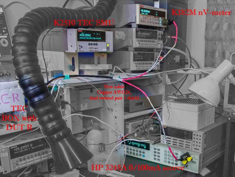
Made a new cable to test both ideas if we see improvement:
1. Used 1m long 4-conductor cable AWG24-ish with twisted pairs, single strand copper wires. All four wires freshly cut and soldered to shunt (this time HP 3458A 0.1 ohm 4W). Then cable with intact jacket exits TEC box, going about 30cm out and branches to two heads. One twisted pair (still with foil shield) goes to BNC on current source. Second twisted pairs soldered to "Cannon"-type connector, going to Keithley 182-M.


2. Python code was modified to perform "OCOMP" 2-point measurement on each point, such as:
Initial setup, current source (LTZ-powered HP 3245A, able to source 100mA) and K182 controlled by GPIB Pi.
Current source set to 0 mA, Soaking 15 seconds. K182 is nulled, 30mV range used.
Current source set to 100mA, data collection started.
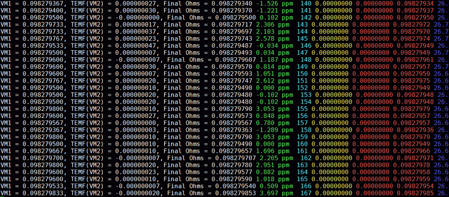
Each sample : Current source set to 100mA, delay 1 second. Three samples taken and averaged to VM1 value. Then Current source set to 0 mA (range unchanged), delay 1 second. Three samples taken and averaged to VM2 value. VM2 subtracted from VM1 and resistance value calculated, assuming current is stable (source confirmed to be stable within 2ppm over 24h).
Each calculation logged for overview:


Tomorrow after some 20+ hours I'll have full ramp data to study :)

 
YouTube | Metrology IRC Chat room | Let's share T&M documentation? Upload! No upload limits for firmwares, photos, files.
 
The following users thanked this post: CalMachine

Offline TiNTopic starter

  • Super Contributor
  • ***
  • Posts: 4543
  • Country: ua
    • xDevs.com
Re: Characterization and measurements for low-resistance shunts?
« Reply #17 on: February 08, 2017, 04:19:52 am »
Data came. Looking much better. This is HP 3458 #362 100 mOhm shunt, used for 1A range.
And -5.2 ppm/K figure sounds about right.


Now I will go back to 20 mOhm VCS shunt and test same. HP 3245A limited to 100mA, so max output voltage will be ~2mV.
We will see TEMF issues easy on this one.
« Last Edit: February 08, 2017, 10:32:50 am by TiN »
YouTube | Metrology IRC Chat room | Let's share T&M documentation? Upload! No upload limits for firmwares, photos, files.
 

Offline CalMachine

  • Frequent Contributor
  • **
  • Posts: 477
  • Country: us
  • Metrology Nut
Re: Characterization and measurements for low-resistance shunts?
« Reply #18 on: February 09, 2017, 12:19:28 am »
Data came. Looking much better. This is HP 3458 #362 100 mOhm shunt, used for 1A range.
And -5.2 ppm/K figure sounds about right.


Now I will go back to 20 mOhm VCS shunt and test same. HP 3245A limited to 100mA, so max output voltage will be ~2mV.
We will see TEMF issues easy on this one.

(still in the middle of watching it, so I might be speaking too soon)  But, your freshly new working EM-A10 with your 2002 should handle that 2 mV drop like a champ! :-+
All your volts are belong to me


Share me

Digg  Facebook  SlashDot  Delicious  Technorati  Twitter  Google  Yahoo
Smf