Author Topic: FET selection process for precision circuits?  (Read 9415 times)

0 Members and 1 Guest are viewing this topic.

Offline TiNTopic starter

  • Super Contributor
  • ***
  • Posts: 4543
  • Country: ua
    • xDevs.com
FET selection process for precision circuits?
« on: April 25, 2018, 10:45:29 am »
Lot of precision low-noise amplifiers are based around composite designs are using FET input stages to obtain lowest possible noise.

Here is one of such circuits, with dual JFET on the input stage, infamous Linear Systems LSK389.


But often high-performance JFETs are hard to buy for hobby-level experimenting, so alternative tinkerer would be considering to use available FETs and do matching and selecting of the suitable samples by hand. However question arise, which parameters would be the priority for selection in low-noise high-gain amplifier application, like this one?

This topic wasn't covered much in details so far, perhaps we can discuss criteria's and methodology behind picking FETs?

To support the claims, I'd like to donate number of hours into testing and defining somewhat useful toolkit, to perform such selection easier for the community.
In the end this may result in open-source python app, that would talk to GPIB instruments to perform the required tests automagically and give a report "FET A matching to FET B within x.x %". Typical instruments for the task are SMUs, so I can support stuff like Keithley 2400 series, which many of nuts here already have. For initial tests I'll however use Agilent 4142B with four SMUs, so we can do any possible test.

To get started, I connected random JFET from dead analog Keithley 2001 board (supposed to be 2N4416 N-channel JFET), and plot the I-V curve:


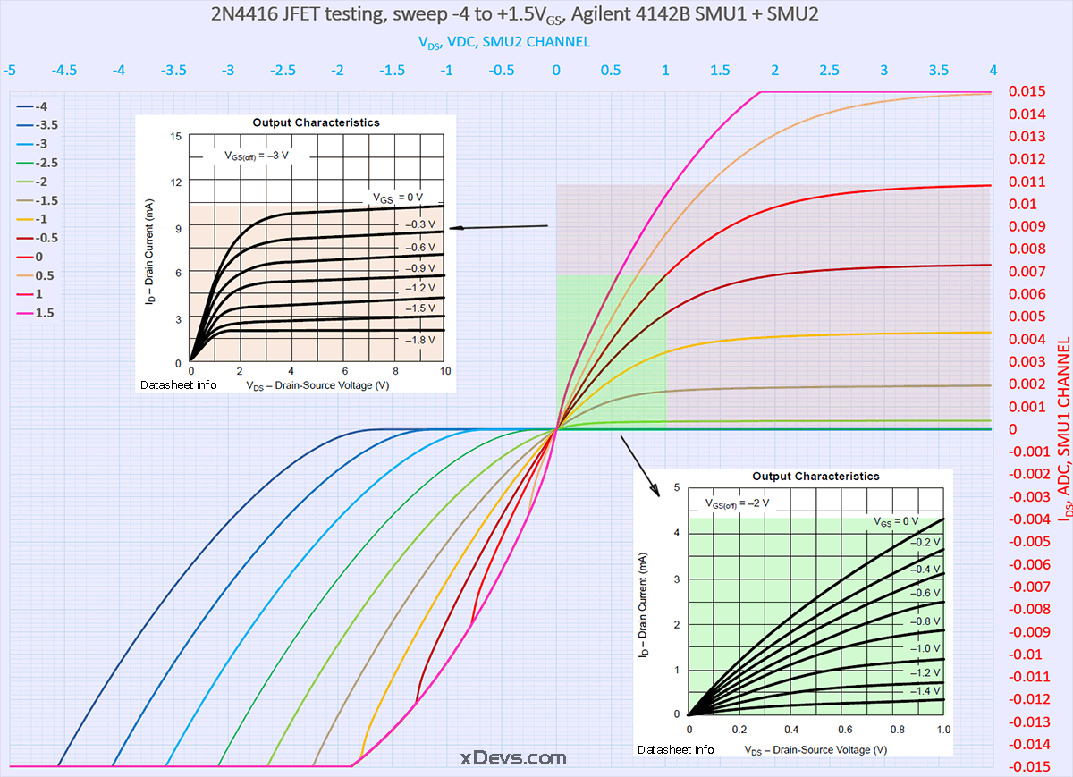
Excel-file on click.

Measurement result agree to datasheet curves well, so I can do next steps, if there are any suggestions. I have started this thread, because this also fits my current need to test unknown JFETs used in broken Keithley 2182A nanovolt-meter front end, so I'd like to use same setup to characterize them and see what their failure mode (input stage was overloaded with high-voltage surge).
YouTube | Metrology IRC Chat room | Let's share T&M documentation? Upload! No upload limits for firmwares, photos, files.
 
The following users thanked this post: Vgkid

Offline TiNTopic starter

  • Super Contributor
  • ***
  • Posts: 4543
  • Country: ua
    • xDevs.com
Re: FET selection process for precision circuits?
« Reply #1 on: April 25, 2018, 10:55:42 am »
rsvd for more data plots
YouTube | Metrology IRC Chat room | Let's share T&M documentation? Upload! No upload limits for firmwares, photos, files.
 

Offline TiNTopic starter

  • Super Contributor
  • ***
  • Posts: 4543
  • Country: ua
    • xDevs.com
Re: FET selection process for precision circuits?
« Reply #2 on: April 25, 2018, 10:57:05 am »
And rsvd for summary and app code.
YouTube | Metrology IRC Chat room | Let's share T&M documentation? Upload! No upload limits for firmwares, photos, files.
 

Offline lukier

  • Supporter
  • ****
  • Posts: 634
  • Country: pl
    • Homepage
Re: FET selection process for precision circuits?
« Reply #3 on: April 25, 2018, 11:16:45 am »
Interesting stuff. Let me know if you need any help, I could do some tests on K2400.

I don't have Agilent 4142B, only one K2400 so I would use that to sweep and use something like Agilent 6632B to set the Vgs.

When I was repairing my Fluke 5440B I boght a bunch of various JFETs  (BF256B,J105,J107,J109,J111,J112,J113,J175_D26Z), so maybe it would be interesting to characterize those.
 

Online Alex Nikitin

  • Super Contributor
  • ***
  • Posts: 1173
  • Country: gb
  • Femtoampnut and Tapehead.
    • A.N.T. Audio
Re: FET selection process for precision circuits?
« Reply #4 on: April 25, 2018, 11:48:30 am »
Don't put too much effort into these measurements. For most practical purposes a matching of the Vgs to less than 2% at the required working point (Vds, Id) and a reasonably constant ambient temperature (for the same type, make and ideally batch JFETs, obviously) is quite sufficient. Better matching would require at the very least a good control of the die temperature (not easy).

Cheers

Alex
 
The following users thanked this post: zhtoor

Offline ap

  • Frequent Contributor
  • **
  • Posts: 282
  • Country: de
    • ab-precision
Re: FET selection process for precision circuits?
« Reply #5 on: April 25, 2018, 01:49:13 pm »
Ilya,

the main issue re. the behaviour of the JFET as an input stage for the 2182A is its voltage noise density at low frequencies. Along with this goes operating current, input capacitance... For really low noise, the choice is limited. The best is you consult the latest edition of The AOE, lots of test data and more included there.

cheers
Metrology and test gear and other stuff: www.ab-precision.com
 

Offline zhtoor

  • Frequent Contributor
  • **
  • !
  • Posts: 337
  • Country: pk
Re: FET selection process for precision circuits?
« Reply #6 on: April 25, 2018, 02:00:45 pm »
hello,

low noise JFET's:-

LSK489, LSJ689, IF3601 ($$!) etc. they come pre-matched and are reasonably priced @ www.micross.com
i recently bought 12X LSK489's for GBP 100.
as far as testing / characterization goes, the *real* part would be noise testing of these parts, and picking / binning lower noise parts from 2N4416
2N4117 populations.

best regards.

-zia
« Last Edit: April 25, 2018, 02:13:42 pm by zhtoor »
 

Offline TiNTopic starter

  • Super Contributor
  • ***
  • Posts: 4543
  • Country: ua
    • xDevs.com
Re: FET selection process for precision circuits?
« Reply #7 on: April 25, 2018, 02:23:29 pm »
ap
That was my thinking too, yet my unit used 2N7000 on path A/B switching and selected 2SK170 pairs as main input stage for preamps.
Not that special, as I might suspected originally.

zhtoor
Yep, I bought bunch of LSK's last year from www.micross.com, had zero issues and prompt delivery.

Actually right now I have one LSK389A in 2182A stage for meter repair troubleshooting, so hence this thread existance. I'm researching what would be best route of action to properly test the replacement, and not to degrade original circuit performance. I'd expect eventually I'll end up making Jim Williams preamp unit for the JFET noise testing as well, however I'm not sure that would be good enough for lowest noise JFETs either. At least I already have all parts, including wet slug 1300uF capacitors (tested leakage <2nA at 10V bias).
YouTube | Metrology IRC Chat room | Let's share T&M documentation? Upload! No upload limits for firmwares, photos, files.
 

Offline zhtoor

  • Frequent Contributor
  • **
  • !
  • Posts: 337
  • Country: pk
Re: FET selection process for precision circuits?
« Reply #8 on: April 25, 2018, 02:28:11 pm »
including wet slug 1300uF capacitors (tested leakage <2nA at 10V bias).

where the hell did you get those? me being in pakistan can only *drool* on those   :'(

and imagine testing a part with ca. 1-2 nv/rtHz noise, now THAT would require some serious GAIN!
probably domain of nanovoltmeters or amplifier modules from em-electronics.

best regards.

-zia
« Last Edit: April 25, 2018, 02:33:47 pm by zhtoor »
 

Offline TiNTopic starter

  • Super Contributor
  • ***
  • Posts: 4543
  • Country: ua
    • xDevs.com
Re: FET selection process for precision circuits?
« Reply #9 on: April 25, 2018, 02:37:10 pm »
I was hunting for the caps for years before I got them. Of course if someone need urgently, there are some on mouser :).
EM A10 should do the job too.

Here is 2182A LNA preamp, in case somebody need memory refresh. It is used only on 10mV range on CH1, from what I see on schematics so far.
I have used AD MAT12A instead of LM394 for now, as I have not sourced LM394 yet.

YouTube | Metrology IRC Chat room | Let's share T&M documentation? Upload! No upload limits for firmwares, photos, files.
 
The following users thanked this post: zhtoor

Offline zhtoor

  • Frequent Contributor
  • **
  • !
  • Posts: 337
  • Country: pk
Re: FET selection process for precision circuits?
« Reply #10 on: April 25, 2018, 02:41:56 pm »
an opensource EM A10 anybody?  :-DD

i hear they use low noise inductive amplification / chopper using a transformer.
now here we would need some serious copper work or CdSn solder.

best regards.

-zia
 

Offline rhb

  • Super Contributor
  • ***
  • Posts: 3481
  • Country: us
Re: FET selection process for precision circuits?
« Reply #11 on: April 25, 2018, 03:38:51 pm »
Measurement of the noise figure of a transistor is typically done with  a calibrated noise source for high frequencies.  A noise figure meter is optional, but makes the task easier.  Fundamentally what you do is measure the output noise with and without the diode noise generator on.

For low frequencies a sine wave source is recommended.

Calibrated diode noise sources are quite expensive.  NIST level calibration is done relative to resistors at specified temperatures with a frequency selective measuring system.

The best reference I have is:

"Low Noise electronic Design"
Motchenbacher and Fitchen
Wiley 1973

which devotes all of chapter 14 to the measurement problem.  I'm sure that Keysight has some good application notes on the subject and there is AoE.

Within the frequency limits imposed by sampling rate, you can evaluate noise by taking two measurements and comparing the crosscorrelation at zero lag to the autocorrelations at zero lag.  If you're using an integrating ADC, you need to take the aliased energy.  As your measurement system produces noise, you need a precision attenuator between the measurement system and the transistor.

An eBay search on diode noise sources should make clear the reason for my interest in an OSHW version of Franco Rota's design. The calibration problem is an unresolved issue.  I only recently took an interest in being able to measure noise figures, so I've not devoted much thought to the problem.

If the output is going to an integrating ADC e.g. 3458A, then you can directly measure the noise using an ADC such as in the LPC4370 which is a 12 bit 80 MS/S single channel ADC.  The aliased noise falls below 1 ppm of the peak at around 3 MHz for PLC=10.  You can evaluate the peak values of sin(f)/f to decide how high you want to go. Long data records will get you additional bits, but each additional bit requires twice as long a measurement, so large improvements come at a steep price.

If you simply want to select the best device from a set, an RF power comparison bridge is probably the best option. Mount sockets on a high quality PCB in a CE circuit with shielded resistors on the inputs.  Everything needs to be scrupulously clean and symmetric.  Null the bridge, swap devices and null again.  Keep the lowest noise unit and repeat.  Obviously lots of shielding is required both electric and magnetic.

I'll send chapter 14 by PM.
 

Online Kleinstein

  • Super Contributor
  • ***
  • Posts: 14192
  • Country: de
Re: FET selection process for precision circuits?
« Reply #12 on: April 25, 2018, 04:11:40 pm »
Noise testing is best done in building a simple amplifier (single JFET or with a pair) with defined gain with the JFETs under test. So it is about measuring the much higher noise at the amplifiers output. The interesting range is likely more like 1 Hz to maybe 1 kHz.  As for a comparison not absolute values are needed, this should be relatively easy, e.g. by simple amplification and sending the data to a fast DMM and doing the rest in software on sampled data.

In a feedback amplifier in the moderate frequency range, gain is usually known good enough. So no special calibration source would be needed. Resistor noise of something like an extra 100 K at the input should be a sufficient test to check.

With JFETs in TO92 case there is not that much choice anymore. There are a few new low noise JFETs in SOT23 case. I don't expect the choice of FETs to be so critical - so other parameters like input capacitance likely do not have to match the original very close.

With a set of 4 JFETs as 2 in parallel each one can compensate some of the differences.
 
The following users thanked this post: TiN

Offline RandallMcRee

  • Frequent Contributor
  • **
  • Posts: 541
  • Country: us
Re: FET selection process for precision circuits?
« Reply #13 on: April 25, 2018, 06:02:55 pm »

Best information source I have seen on JFET noise is AoE 3rd edition.

BTW that chopper amplifier is old technology, here is an updated one (attached)

Five times lower noise.

From this site: http://www.janascard.cz/PDF/Design%20of%20ultra%20low%20noise%20amplifiers.pdf

 
The following users thanked this post: TiN, zhtoor, razvan784

Offline David Hess

  • Super Contributor
  • ***
  • Posts: 16612
  • Country: us
  • DavidH
Re: FET selection process for precision circuits?
« Reply #14 on: April 25, 2018, 09:49:25 pm »
But often high-performance JFETs are hard to buy for hobby-level experimenting, so alternative tinkerer would be considering to use available FETs and do matching and selecting of the suitable samples by hand. However question arise, which parameters would be the priority for selection in low-noise high-gain amplifier application, like this one?

My semiconductor physics fu is weak and I never stayed at a Holiday Inn Express but ...

Ultimately I think what you are looking for is the figure of merit equal to the ratio between transconductance and square root of the input capacitance.  So devices with a higher transconductance, which goes along with the lower noise contributed by the lower source resistance which is the equivalent of the emitter resistance in a bipolar transistor, for a given input capacitance are lower noise.

For example using the above rule, if I replace one JFET with two JFETs in parallel (and double the total source current to maintain the same transconductance for each part), the transconductance is doubled (the source resistance is halved) while the square root of the total input capacitance increases by 1.414 times.  The figure of merit has increased 1.414 times corresponding to a decrease in input voltage noise of 1.414 times which is what I would expect with two identical amplifiers in parallel.

Obviously there is a lot more to it when designing a low noise JFET including the channel geometry but if I was estimating from the characteristics given in datasheets where noise and design details are not included, this is where I would start.

and imagine testing a part with ca. 1-2 nv/rtHz noise, now THAT would require some serious GAIN!
probably domain of nanovoltmeters or amplifier modules from em-electronics.

As Kleinstein points out, the low noise transistor is configured to amplify its own noise first, and then the amplified output noise is measured which is much easier.  Since we know the gain, we can then calculate the input referred noise.
« Last Edit: April 26, 2018, 10:12:23 am by David Hess »
 
The following users thanked this post: TiN

Offline IconicPCB

  • Super Contributor
  • ***
  • Posts: 1534
  • Country: au
Re: FET selection process for precision circuits?
« Reply #15 on: April 26, 2018, 09:12:29 am »

This is every young maidens dream come true

https://www.radiomuseum.org/r/telequip_curvetracer_ct71ct_7.html
 

Offline rhb

  • Super Contributor
  • ***
  • Posts: 3481
  • Country: us
Re: FET selection process for precision circuits?
« Reply #16 on: April 26, 2018, 01:21:15 pm »
I'm a little puzzled at curve tracers appearing in a discussion of noise figure measurement.

Generally noise figure becomes important above 30 MHz.  Below that atmospheric noise dominates so there really is no need for low noise amplifiers in RF.  Instrumentation is a very different set of issues.

I think it worth noting that the noise performance of a device is intimately associated with the circuit in which it is used. The volume I cited previously goes into almost 300 pages of details on the subject treating each type of amplifier.
 

Offline eurofox

  • Supporter
  • ****
  • Posts: 873
  • Country: be
    • Music
Re: FET selection process for precision circuits?
« Reply #17 on: April 26, 2018, 02:12:16 pm »
eurofox
 

Offline rhb

  • Super Contributor
  • ***
  • Posts: 3481
  • Country: us
Re: FET selection process for precision circuits?
« Reply #18 on: April 26, 2018, 02:31:09 pm »
I have one.  It's quite nice. It takes a while to produce a set of curves but I thought it quite a good deal.  I bought all of their top line testers except for the cable tester because I already had both ethernet and audio cable testers besides an audio tester I designed and built 30+ years ago.

I've not subjected them to any rigorous testing for lack of anything to compare them to.
 

Offline David Hess

  • Super Contributor
  • ***
  • Posts: 16612
  • Country: us
  • DavidH
Re: FET selection process for precision circuits?
« Reply #19 on: April 26, 2018, 03:18:04 pm »
I'm a little puzzled at curve tracers appearing in a discussion of noise figure measurement.

Generally noise figure becomes important above 30 MHz.  Below that atmospheric noise dominates so there really is no need for low noise amplifiers in RF.  Instrumentation is a very different set of issues.

I agree however the context is in connection with low noise low frequency instrumentation.  What characteristics can be measured with a curve tracer that correlate with noise performance?  I indicated transconductance but I think input capacitance also matters.  What commonly available JFETs are suitable for low noise low frequency instrumentation applications?

Quote
I think it worth noting that the noise performance of a device is intimately associated with the circuit in which it is used. The volume I cited previously goes into almost 300 pages of details on the subject treating each type of amplifier.

In this case we have no attempt at input impedance matching and the circuits are all pretty much the same with some variation of a common source amplifier.
 
The following users thanked this post: TiN

Offline rhb

  • Super Contributor
  • ***
  • Posts: 3481
  • Country: us
Re: FET selection process for precision circuits?
« Reply #20 on: April 26, 2018, 04:31:35 pm »
Here is the portion of the book most relevant to the question at hand.  I think this falls within fair use.  Note that JFETs pose slightly different requirements than BJTs.

On reflection, one might simply be able to measure Vrms at the output of a CE amplifier with a shielded resistor across the inputs to grade the units.
 

Offline Cerebus

  • Super Contributor
  • ***
  • Posts: 10576
  • Country: gb
Re: FET selection process for precision circuits?
« Reply #21 on: April 26, 2018, 04:42:35 pm »
I'm a little puzzled at curve tracers appearing in a discussion of noise figure measurement.

Perhaps because you're the only person who thinks this is an exclusive discussion of noise figure testing?

The subject heading was: "FET selection process for precision circuits?". Noise might come into it eventually, but matching differential pairs was TIN's starting point.
Anybody got a syringe I can use to squeeze the magic smoke back into this?
 

Offline TiNTopic starter

  • Super Contributor
  • ***
  • Posts: 4543
  • Country: ua
    • xDevs.com
Re: FET selection process for precision circuits?
« Reply #22 on: April 30, 2018, 04:30:39 am »
The subject heading was: "FET selection process for precision circuits?". Noise might come into it eventually, but matching differential pairs was TIN's starting point.

Indeed, as precision != necessary low noise :).

I checked original JFETs (2SK170) from meter and they are indeed very dead (one shorted, three open), so we don't know what parameter Keithley used to match those transistors originally. So I assume it is Vgs for now.

Did some tests with updated code on new 2N4392's (from Digikey) and LSK389A. Tested FET pairs at same time, by using SMU1-2 for one FET, and SMU3-4 for second.
Sources connected to GNDU sink and IGS limited to 1uA.
Also ordered few dozen of LSK170 from Micross, by the time they arrive I shall have test setup refined and ready for matching.

YouTube | Metrology IRC Chat room | Let's share T&M documentation? Upload! No upload limits for firmwares, photos, files.
 

Online Kleinstein

  • Super Contributor
  • ***
  • Posts: 14192
  • Country: de
Re: FET selection process for precision circuits?
« Reply #23 on: April 30, 2018, 06:34:16 am »
The main parameter for matching is likely U_GS for a fixed given U_DS and current (e.g. 5 V and 3 mA). As the amplifier uses a kind of chopping / CAZ, the matching might actually not be that critical.  With two pairs there can also be a compensation with a lot of choices to find suitable sets of 4, even if they don't make up good pairs. The two LSK170 curves shown already seem to be a pretty good match.
In the CAZ like circuit, an offset of the FET pair might end up as extra bias.

I would still check the noise, as a noisy transistor can ruin the amplifier and there is a chance to have some noisy ones. Just a crude test with a simple amplifier circuit should be enough. For a nV meter noise also gets important.

I am not sure if matching / selecting of the 2N7000 is needed to keep switching spikes of the chopper small.
 

Offline TiNTopic starter

  • Super Contributor
  • ***
  • Posts: 4543
  • Country: ua
    • xDevs.com
Re: FET selection process for precision circuits?
« Reply #24 on: April 30, 2018, 10:10:19 am »
2N7000's are not marked as selected in Keithley's BOM. I tried LSK389C (higher IDSS current), and meter show huge offset (127mV) in readings.. More to test.
YouTube | Metrology IRC Chat room | Let's share T&M documentation? Upload! No upload limits for firmwares, photos, files.


Share me

Digg  Facebook  SlashDot  Delicious  Technorati  Twitter  Google  Yahoo
Smf