Got a new toy..
Since mostly these units require some tweaking and modifications, I think this should belong to here, rather than just repair section..
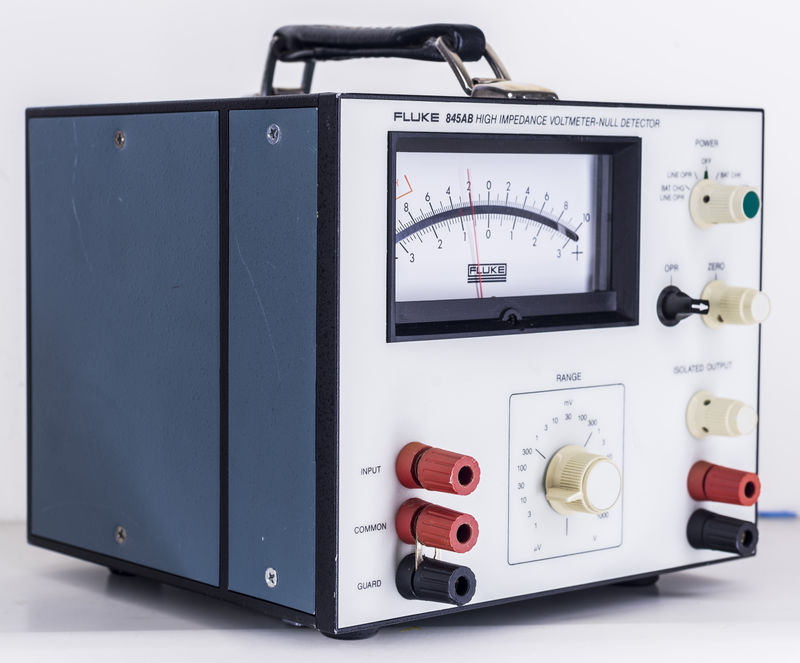
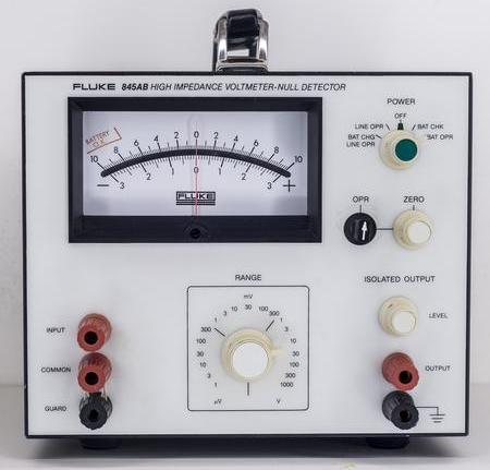
Really clean and nice condition outisde:
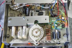
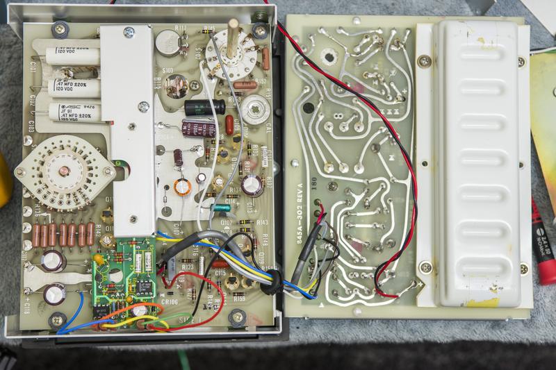
Let's see inside:
Guarded area:
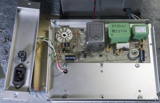
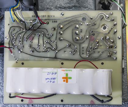
Woohoo

I was expected to see infamous neon tubes, light guides and photoresistor chopper amplifier, but was greeted insteal with alien-looking green PCB with micropower regulator Linear LT1120CN8 and few HP 2731 optocouplers(?) !
LT1120 dates with 1993 week 52. Is it that optically-isolated Bilateral Analog chopper, which mentioned in Fluke 845AB manual's note in 7/1993 print?
Repairs* Meter does not read anything in BAT OPR mode. It's just dead on zero, like no power is supplied, even though BAT CHK shows good battery
* In LINE OPR mode meter is unable to zero on ranges below 30µV
First issue was resolved by fixing blown track on power PCB.
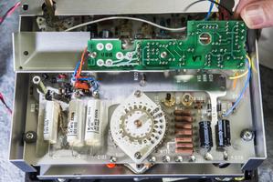
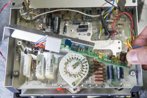
As usual with equipment with age over 15 years I replace all electrolytic capacitors to avoid electrolyte leaks and further desctruction.
There is plenty space inside, so I just used usual good quality Chemicon radial capacitors instead of axial. I used 470uF 63V instead of original 470uF 25V and 6.3V caps.
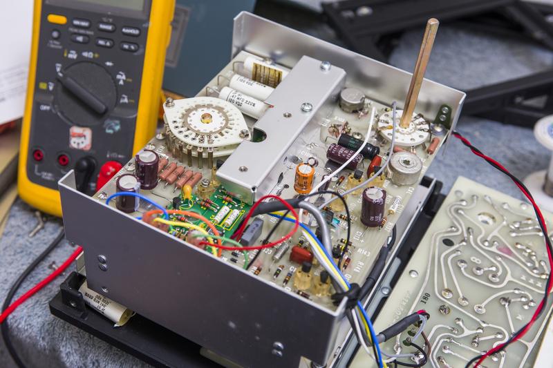
Green PCB with chopper assembly have blue multiturn trimmer pot, accessible from the side. That pot adjustment allowed to shift zero, so now meter can be zeroed on lowest 1 µV range.
Test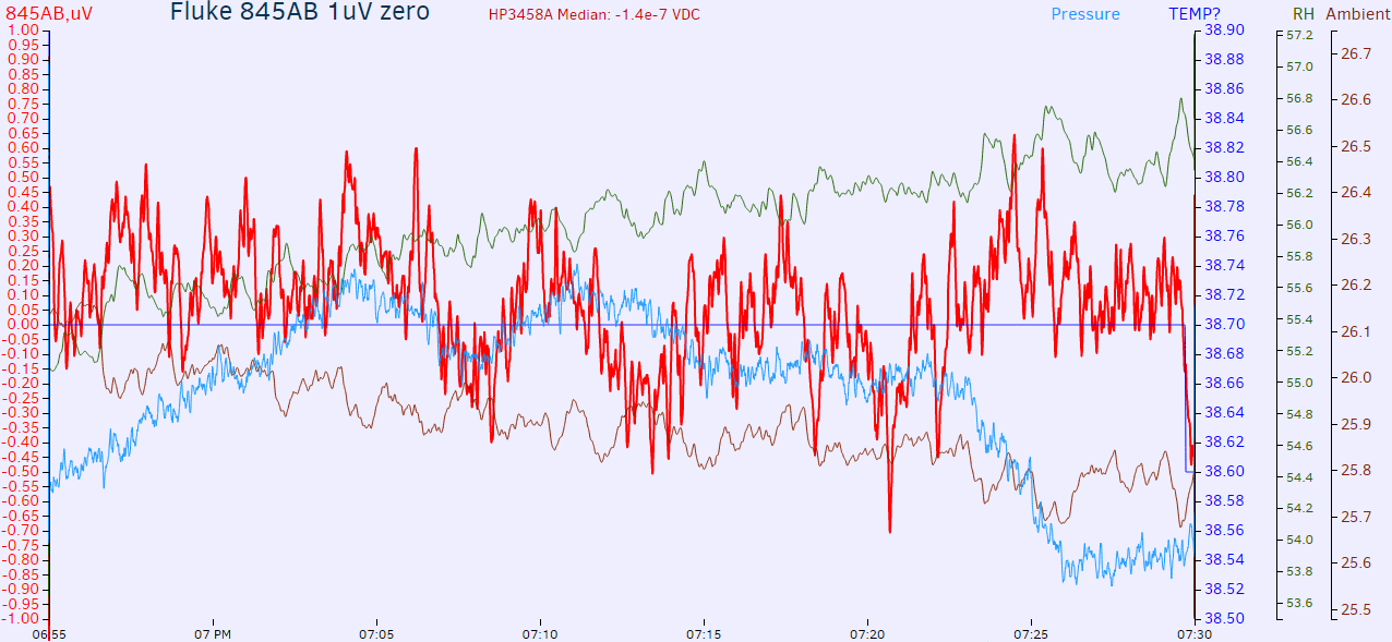
Settings: Fluke 845AB Range: 1 µV, OPR switch = ZERO, 3458A DCV auto, 10 NPLC, AZERO ON
I will post YouTube video later.
Perhaps worth to reverse that green PCB schematics?
Future plans:
* Add backlight for meter
* Remove input resistance to have high impedance input
* Study chopper operation ,perhaps replace with something more stable?
* Ultimate mod - replace analog meter with digital PCB module with battery-powered Sigma-Delta ADC to show readings in digital?

+ As usual
article with bit more details on my site.


