Author Topic: Live design flow of 'FX' 10V LTZ1000A-based reference  (Read 16959 times)

0 Members and 1 Guest are viewing this topic.

Offline mimmus78

  • Supporter
  • ****
  • Posts: 676
  • Country: it
Re: Live design flow of 'FX' 10V LTZ1000A-based reference
« Reply #25 on: November 11, 2017, 06:00:38 pm »
To my knowledge, there is no 'special' layout from LTC, I think what you are referring to was an incorrect board layout and he had to mount the LTZ on the backside of the PCB to make it work.  It wasn't discovered until after the boards were made, it happens.
Yes, he wasn't the only one ...

Inviato dal mio Nexus 6P utilizzando Tapatalk


Offline pitagoras

  • Regular Contributor
  • *
  • Posts: 116
  • Country: fr
Re: Live design flow of 'FX' 10V LTZ1000A-based reference
« Reply #26 on: November 26, 2017, 02:56:36 pm »
The boards are back from manufacturing and the saga continues with livestreaming the assembly of the pcb


Offline TiN

  • Super Contributor
  • ***
  • Posts: 4543
  • Country: ua
    • xDevs.com
Re: Live design flow of 'FX' 10V LTZ1000A-based reference
« Reply #27 on: November 27, 2017, 03:02:01 am »
First FX board is alive.

After few hurdles due to late night assembly (wrong resistor value, 1KOhm instead of 75Kohm, lol), LTZ section is working.
I couldn't be bothered to wait for initial few hundred hours warm-up, so started tempco curve right away.

Resistors used for test: AE 1K + AE 15K, 220 ohm AE + 330 ohm S102J + 900 ohm S102J (115 ohm), 2 x 75Kohm PTF56 <5ppm/K (tested).

.

This is without 400K TC compensation resistor, so good start I'd say.

Two data lines are since I connected reference 7V output to both 3458A for better confidence.
« Last Edit: November 27, 2017, 12:03:06 pm by TiN »
YouTube | Metrology IRC Chat room | Let's share T&M documentation? Upload! No upload limits for firmwares, photos, files.
 
The following users thanked this post: nidlaX, hwj-d

Offline TiN

  • Super Contributor
  • ***
  • Posts: 4543
  • Country: ua
    • xDevs.com
Re: Live design flow of 'FX' 10V LTZ1000A-based reference
« Reply #28 on: November 27, 2017, 05:18:23 pm »
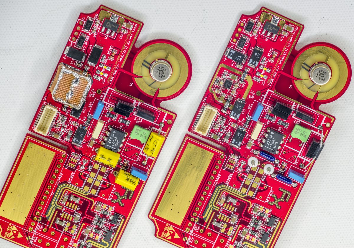
Assembled two more modules, for total 3 units.

First, comparison to well known HP 3458A A9 DC Reference module and my old KX public version LTZ1000(A) module.


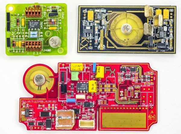
I'm missing opamp, resistor network and MELF resistors for the 7V->10V output amplifier section, so that will be assembled after parts arrive. Currently I can test tempco and establish intermediate 7V output, and get a glimpse on initial stability, to make sure no funny business happenin.


Little section with DFN chip is low-noise Linear LT3042 +11V linear regulator, that powers LT1013A and LTZ1000A chip.
Output amp powered directly from input power entry (power source for this module is +12/-12V VRLA battery array).
There are just TVS at the input and few bulk tantalum capacitors.

20-pin connector provide isolated +3.3V to calibration data EEPROM (I2C 24128, U7) and +5V supply to MAX6610 (U4 in center).
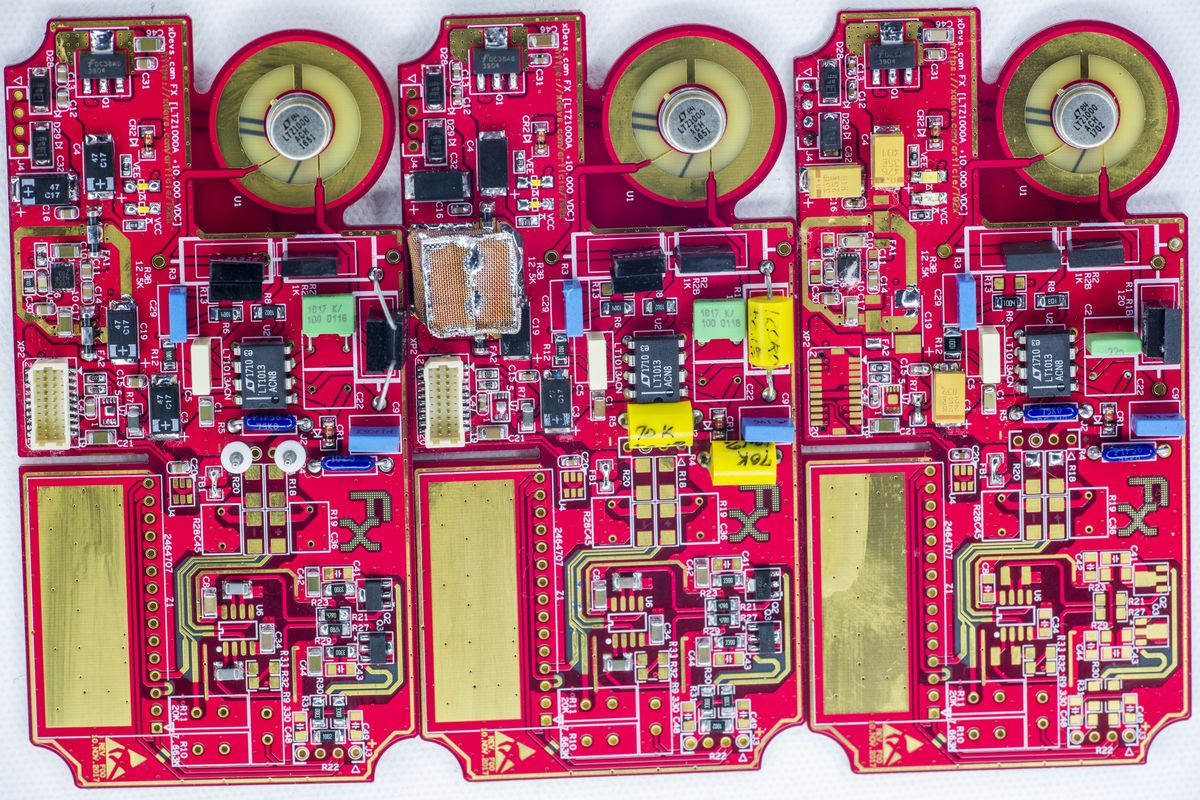


Configurations:

FX 001 : LTZ1000ACH, 51 week 2016, 1K AE YB BMF, 20K S102J + 34.8K S102K, 330R + 300R + 522.2R S102, 2 x PTF56 75K (tested <-6ppm/K).
FX 002 : LTZ1000ACH, 51 week 2016, 1K AE YB BMF, 28.5K S102J + 28.5K S102K, 120R Edwin PWW, 2 x Edwin PWW 70K
FX 003 : LTZ1000ACH, 51 week 2016, 1K AE XB BMF, 15K AE XB BMF, two S102 in parallel to get 132R
« Last Edit: November 27, 2017, 05:46:04 pm by TiN »
YouTube | Metrology IRC Chat room | Let's share T&M documentation? Upload! No upload limits for firmwares, photos, files.
 
The following users thanked this post: Echo88, nidlaX

Offline Echo88

  • Frequent Contributor
  • **
  • Posts: 826
  • Country: de
Re: Live design flow of 'FX' 10V LTZ1000A-based reference
« Reply #29 on: November 27, 2017, 07:11:21 pm »
Nice!  :-+
 

Offline nidlaXTopic starter

  • Frequent Contributor
  • **
  • Posts: 663
  • Country: us
Re: Live design flow of 'FX' 10V LTZ1000A-based reference
« Reply #30 on: November 27, 2017, 10:02:02 pm »
Very nice, updated the first post.
 

Offline TiN

  • Super Contributor
  • ***
  • Posts: 4543
  • Country: ua
    • xDevs.com
Re: Live design flow of 'FX' 10V LTZ1000A-based reference
« Reply #31 on: December 04, 2017, 07:38:00 pm »
Got Digikey parts today and continued to assemble FX module, this time output stage to get 10V.

Livestream.

There was a hiccup (no wonder, 2am not best time to debug analog precision circuits), and only after video I discovered my mistake and got proper 10V output.
Now it's already running 30 minutes, hovering around 9.999960 V, with std-dev ~1.8uV (K2182).

P.S. Sorry about low sound level.
YouTube | Metrology IRC Chat room | Let's share T&M documentation? Upload! No upload limits for firmwares, photos, files.
 

Offline Kleinstein

  • Super Contributor
  • ***
  • Posts: 14172
  • Country: de
Re: Live design flow of 'FX' 10V LTZ1000A-based reference
« Reply #32 on: December 04, 2017, 07:57:02 pm »
I don't think the 2182 is good enough to directly measure the noise. Normally the noise of the 10 V signal should be lower than even the HP3458 in the 10 V range. So those 1.8 µV of SD are likely something like 1.6 µV from the 2182 and maybe 0.5 µV from the 10 V reference.

It would be only as a difference to a second reference or with AC coupling that one can get an idea of the noise.
 

Offline TiN

  • Super Contributor
  • ***
  • Posts: 4543
  • Country: ua
    • xDevs.com
Re: Live design flow of 'FX' 10V LTZ1000A-based reference
« Reply #33 on: December 05, 2017, 04:12:05 pm »
I don't think the 2182 is good enough to directly measure the noise.

I thought so too, (3458s were busy measuring resistor's tempco yesterday) but today data shows that 2182 on 10V is quite a performer, not that far off 3458A or 2002.

Attached graph capture, no sample averaging applied.

Settings:
Blue and green : 3458A, NPLC200, 10VDC, AZER ON
Red: 2002, NPLC50, 20VDC, AZER SYNC, DFILT MOV 10, LSYN ON
Urple: 2182 (non-A), NPLC5, AZER ON, LSYNC ON, FAZ ON, LPAS ON, DFILT ON, 10VDC, Channel 1

Reference output stage is powered from +12.6V (K2306) and -12.6V (K2400). 7V Zener section is powered by onboard LT3042 +11.0V, regulated from +12.6V rail.

CSV-data LIVE.
YouTube | Metrology IRC Chat room | Let's share T&M documentation? Upload! No upload limits for firmwares, photos, files.
 

Offline Kleinstein

  • Super Contributor
  • ***
  • Posts: 14172
  • Country: de
Re: Live design flow of 'FX' 10V LTZ1000A-based reference
« Reply #34 on: December 05, 2017, 04:57:53 pm »
From the board pictures, the 2182 ADC / reference part looks rather similar to the ADC in the 2010. The 2010 is known to be rather low noise, despite using only a LM399 reference. As a  nV meter the input amplifier of the 2182 is expected to be very low noise, so the performance should be good in the other ranges too, not just the 10 V. It's probably even more impressive in the 100 mV and 10 mV ranges.

The comparison is a little tricky, as the digital filtering can be a little misleading.
 

Offline TiN

  • Super Contributor
  • ***
  • Posts: 4543
  • Country: ua
    • xDevs.com
Re: Live design flow of 'FX' 10V LTZ1000A-based reference
« Reply #35 on: December 07, 2017, 01:04:37 am »


Initial testing for tempco started, using 10V output stage.


I need to move one of the meters to 7V output before the stage, so we can see impact on tempco from gain stage alone.  :phew:

EDIT: And complete run:


Clear to see when we ran out of LTZ oven margin (output skyrocketed +140ppm).

« Last Edit: December 07, 2017, 01:12:15 pm by TiN »
YouTube | Metrology IRC Chat room | Let's share T&M documentation? Upload! No upload limits for firmwares, photos, files.
 

Offline VintageNut

  • Frequent Contributor
  • **
  • Posts: 534
  • Country: 00
Re: Live design flow of 'FX' 10V LTZ1000A-based reference
« Reply #36 on: December 07, 2017, 10:32:25 am »
I agree. If the LTZ is 0.0x ppm / deg c, then the resistors and/or opamp(s) around the LTZ are causing the 10V to change with temp.

For these these modules to be really useful, they have to be better than a 731B which I think mandates that the entire board be in a temp controlled oven.

From a cost standpoint, a 732B has such a high price that spending a few more hundreds of dollars on a temp controlled oven enclosing your reference is a good idea. If the entire ovenized reference is less than $1,000, then that is a very successful DIY design. I would want one of those. Without the oven, the reference is no more stable than my qty of $250 731B.

Please correct me if I have made any incorrect points above.
working instruments :Keithley 260,261,2750,7708, 2000 (calibrated), 2015, 236, 237, 238, 147, 220,  Rigol DG1032  PAR Model 128 Lock-In amplifier, Fluke 332A, Gen Res 4107 KVD, 4107D KVD, Fluke 731B X2 (calibrated), Fluke 5450A (calibrated)
 
The following users thanked this post: zhtoor

Offline TiN

  • Super Contributor
  • ***
  • Posts: 4543
  • Country: ua
    • xDevs.com
Re: Live design flow of 'FX' 10V LTZ1000A-based reference
« Reply #37 on: December 07, 2017, 01:09:40 pm »
For these these modules to be really useful, they have to be better than a 731B which I think mandates that the entire board be in a temp controlled oven.
snip..
Please correct me if I have made any incorrect points above.

Not to nitpick, but what is the tempco of your 731B? Per instruction manual it is specified 1ppm/K. Do you have measurements data?
I'll surely try to get best stability possible out of the module, without external oven.  ;)
YouTube | Metrology IRC Chat room | Let's share T&M documentation? Upload! No upload limits for firmwares, photos, files.
 

Offline Kleinstein

  • Super Contributor
  • ***
  • Posts: 14172
  • Country: de
Re: Live design flow of 'FX' 10V LTZ1000A-based reference
« Reply #38 on: December 07, 2017, 01:50:36 pm »
The 7 V reference module is good even without an extra oven. However the 7 to 10 V stage is only as good as the resistors. In this case it might actually be cheaper to use an oven to stabilize the resistors than hunting for resistors in the 0.1 ppm/K range.

The resistors don't produce much heat, and the power is constant - thus thermal stabilization is not that difficult and does not need high power, if thermal insulation is good. However one still needs long time stable resistors, it is only the TC that can be suppressed to a large part and the humidity effect might be reduced a little, as the hot part will be lower humidity.
In addition to the 7 to 10 V amplifier one might as well stabilize some of the resistors of the LTZ circuit as well, especially the 1 K / 13 K divider.
I kind of miss a switch to change between the raw 7 V and scaled 10 V reference.

The critical parameter of such a reference is usually not the TC, but more like the long time stability. So for quite a few cases just a good temperature sensor could be enough, if the temperature dependence is known for a certain range (e.g. 18 C to 30 C).
 
The following users thanked this post: TiN

Offline TiN

  • Super Contributor
  • ***
  • Posts: 4543
  • Country: ua
    • xDevs.com
Re: Live design flow of 'FX' 10V LTZ1000A-based reference
« Reply #39 on: December 07, 2017, 01:55:57 pm »
There is test point footprint that allow to fanout 7V output from LTZ, so one could add additional pair of binding posts to get raw 7V output, together with 10V output stage output.
Thermal coupling to case is one of the reason to ease on tempco issues, one could stabilize then whole can if desired.  ;D
« Last Edit: December 07, 2017, 01:57:35 pm by TiN »
YouTube | Metrology IRC Chat room | Let's share T&M documentation? Upload! No upload limits for firmwares, photos, files.
 

Offline Dr. Frank

  • Super Contributor
  • ***
  • Posts: 2382
  • Country: de
Re: Live design flow of 'FX' 10V LTZ1000A-based reference
« Reply #40 on: December 07, 2017, 03:16:49 pm »
I agree. If the LTZ is 0.0x ppm / deg c, then the resistors and/or opamp(s) around the LTZ are causing the 10V to change with temp.

For these these modules to be really useful, they have to be better than a 731B which I think mandates that the entire board be in a temp controlled oven.

From a cost standpoint, a 732B has such a high price that spending a few more hundreds of dollars on a temp controlled oven enclosing your reference is a good idea. If the entire ovenized reference is less than $1,000, then that is a very successful DIY design. I would want one of those. Without the oven, the reference is no more stable than my qty of $250 731B.

Please correct me if I have made any incorrect points above.

The 732A/B use an oven for the whole board, because the SZA263/LTFLU is NOT ovenized itself.

Therefore, for a LTZ1000 based reference, which already had been trimmed to around 0.02ppm/K, it would suffice, to build another oven for the 10/7 resistor only, to get <<0.1ppm/K for the 10V output also.
To additionally ovenize any of the LTZ1000 circuit components would probably create problems on the stability of the circuit.

I also think, that such an extended reference could be realized for less than 200 $/€, if the additional oven and a VHD200 may add another 60..80$ to the about 120$/€ for the LTZ1000 board alone.

In the end, my idea for frequent re-calibration of these 10V, is to use any 6 1/2 digits DMM with ratio function, which might give < 2ppm uncertainty due to linearity error, when the raw LTZ1000 is available on the front panel also.

Frank
« Last Edit: December 07, 2017, 03:52:53 pm by Dr. Frank »
 
The following users thanked this post: TiN, e61_phil

Offline TiN

  • Super Contributor
  • ***
  • Posts: 4543
  • Country: ua
    • xDevs.com
Re: Live design flow of 'FX' 10V LTZ1000A-based reference
« Reply #41 on: December 08, 2017, 10:34:33 am »
Reran tempco test, this time with K2002 monitoring direct 7V output before the output stage input. Also this time temperature ramp is +16 to +50C.


Data reveals that nearly all of the temperature coefficient actually derived from the LTZ section, not the output stage.
This was a bit of surprise, considering that I trimmed this output prior to adding output stage to <-0.03ppm/K:-//
Output opamp stage changed thermals and loading to the LTZ output, causing more negative TC?
YouTube | Metrology IRC Chat room | Let's share T&M documentation? Upload! No upload limits for firmwares, photos, files.
 

Offline VintageNut

  • Frequent Contributor
  • **
  • Posts: 534
  • Country: 00
Re: Live design flow of 'FX' 10V LTZ1000A-based reference
« Reply #42 on: December 08, 2017, 06:03:56 pm »
My temp measurements are not from a calibrated system. Just an inexpensive temp display.


deg V  Voltage                   V /  deg C
21.5     9.999954         
22.4     9.9999574      3.77778E-06   
23.1     9.9999614      5.71429E-06   
23.9     9.9999648      4.25E-06   

A bit better than 1 ppm / deg C.  Not consistent over temp. Maybe a better temp system would give a better characterization.

If the entire 731B could be placed into a temp controlled oven, that would be a nice reference. All of the resistors are decades old.
working instruments :Keithley 260,261,2750,7708, 2000 (calibrated), 2015, 236, 237, 238, 147, 220,  Rigol DG1032  PAR Model 128 Lock-In amplifier, Fluke 332A, Gen Res 4107 KVD, 4107D KVD, Fluke 731B X2 (calibrated), Fluke 5450A (calibrated)
 
The following users thanked this post: TiN

Offline TiN

  • Super Contributor
  • ***
  • Posts: 4543
  • Country: ua
    • xDevs.com
Re: Live design flow of 'FX' 10V LTZ1000A-based reference
« Reply #43 on: December 08, 2017, 06:17:59 pm »
.. 1 ppm / deg C.  Not consistent over temp. Maybe a better temp system would give a better characterization.
If the entire 731B could be placed into a temp controlled oven, that would be a nice reference. All of the resistors are decades old.

Hm, seem to be no much difficulty, beating those numbers by factor of 10.
Currently running with 226K compensation resistor. :).
YouTube | Metrology IRC Chat room | Let's share T&M documentation? Upload! No upload limits for firmwares, photos, files.
 

Offline Kleinstein

  • Super Contributor
  • ***
  • Posts: 14172
  • Country: de
Re: Live design flow of 'FX' 10V LTZ1000A-based reference
« Reply #44 on: December 08, 2017, 07:59:47 pm »
If you want to measure a small TC over a small temperature variation, this gives very minute changes. Thus the meter for the measurements could be a problem too. A better temperature reading is likely not yet that important.

Old resistors may help a little for stability. The true value of an old reference comes if there is a good calibration history - this somewhat reflects the price of some $500 for every point.
 
The following users thanked this post: TiN

Offline TiN

  • Super Contributor
  • ***
  • Posts: 4543
  • Country: ua
    • xDevs.com
Re: Live design flow of 'FX' 10V LTZ1000A-based reference
« Reply #45 on: December 09, 2017, 09:06:38 pm »
More on tempco saga..


First time I see myself a positive tempco LTZ output :).
Also "waves" around +30c likely due to me, moving stuff in lab around and turning on/off random gear.

Maybe just a liiiiiitle less compensation and we are in business for some aging and some x00-ish long logging.

If somebody forget, red dashed line is +0.05ppm/K threshold, blue is -0.05ppm/K.
YouTube | Metrology IRC Chat room | Let's share T&M documentation? Upload! No upload limits for firmwares, photos, files.
 

Offline kj7e

  • Frequent Contributor
  • **
  • Posts: 911
  • Country: us
  • Damon Stewart
Re: Live design flow of 'FX' 10V LTZ1000A-based reference
« Reply #46 on: December 10, 2017, 12:18:49 am »

First time I see myself a positive tempco LTZ output :).
Also "waves" around +30c likely due to me, moving stuff in lab around and turning on/off random gear.


What did you change (please include value)?

Funny enough, I see a small bump (about 2uV) right at 30 Deg C transition on my LTZ1000A's as well.
 

Offline TiN

  • Super Contributor
  • ***
  • Posts: 4543
  • Country: ua
    • xDevs.com
Re: Live design flow of 'FX' 10V LTZ1000A-based reference
« Reply #47 on: December 11, 2017, 04:19:35 am »
I don't think value would be much of help, as it is specific for the LTZ used, and each reference need own value for "sweet-spot".

Anyhow, got second module in the action, and ended up with somewhat confusing data.

Everything looked fine and dandy till +32C on positive ramp, and then LTZ direct voltage took off at rate ~+0.03 ppm/K, while 10V output barely changed?
Then after sitting for an hour at +50C flat 10V output started to decline.

Maybe it's the tempco of ESI DB52 used for second-order trim, as ambient temperature changed about -0.7C from same +32c point. But that shouldn't have that much impact.  :-//


Installed fixed resistor in the ref now, and restarted the test again.

Moral of the story: always test ramp up AND ramp down, that can reveal unwanted behaviors like this or hysteresis offsets easily.
Also step response tests do no good for such suddle changes.  ;)
« Last Edit: December 11, 2017, 04:26:37 am by TiN »
YouTube | Metrology IRC Chat room | Let's share T&M documentation? Upload! No upload limits for firmwares, photos, files.
 

Offline TiN

  • Super Contributor
  • ***
  • Posts: 4543
  • Country: ua
    • xDevs.com
Re: Live design flow of 'FX' 10V LTZ1000A-based reference
« Reply #48 on: December 12, 2017, 04:28:41 am »
Retest update with slower 0.05C/minute speed ramp up completed and fixed trim resistor instead of decade.

.

Tempco anyone?  :-DD  :=\

Also attached pre-trim 7V only tempco test from last week, on this same reference.

Voltage versus Box temperature graph:


« Last Edit: December 12, 2017, 04:53:21 am by TiN »
YouTube | Metrology IRC Chat room | Let's share T&M documentation? Upload! No upload limits for firmwares, photos, files.
 
The following users thanked this post: plesa, dr.diesel, kj7e, hwj-d, Pipelie

Offline TiN

  • Super Contributor
  • ***
  • Posts: 4543
  • Country: ua
    • xDevs.com
Re: Live design flow of 'FX' 10V LTZ1000A-based reference
« Reply #49 on: January 07, 2018, 03:08:32 pm »
I've received 3D printed caps from ManateeMafia:


They fit rather nice, just minor tweaking required.


Later this week will finally test output stage performance and trimming options with resistor network.

YouTube | Metrology IRC Chat room | Let's share T&M documentation? Upload! No upload limits for firmwares, photos, files.
 
The following users thanked this post: dr.diesel


Share me

Digg  Facebook  SlashDot  Delicious  Technorati  Twitter  Google  Yahoo
Smf