Author Topic: Ultra Low Noise Reference 2DW232, 2DW233, 2DW23x  (Read 243694 times)

0 Members and 1 Guest are viewing this topic.

Offline Kleinstein

  • Super Contributor
  • ***
  • Posts: 14172
  • Country: de
Re: Ultra Low Noise Reference 2DW232, 2DW233, 2DW23x
« Reply #325 on: December 14, 2016, 04:26:50 pm »
At that noise level, some of the noise could be due to temperature fluctuations and thermal EMF, e.g. at the pins. Quite some of the noise could come from the DMM (internal ref) as well.
I don't see a big difference, except from the difference integration time. There might be minor differences from AZ switching - but this would be more a question of the DMM.

To really judge the quality one would likely need something like a small board and enclosure and possibly even temperature regulation (at least measurement). Only than one can really see the drift over time and hysteresis after temperature excursions. This are likely the main uncertainties, that could still become a problem for some applications.
 

Offline guenthert

  • Frequent Contributor
  • **
  • Posts: 712
  • Country: de
Re: Ultra Low Noise Reference 2DW232, 2DW233, 2DW23x
« Reply #326 on: December 14, 2016, 05:19:55 pm »
Hi,

Today I received a book (Calibration philosophy in practice second edition).
In that they had described little about zener references that confirms that the other diode needs to be in series with the other zener diode.
There is also some info about the 732B.

Pics attached :)
Thanks for the excerpt.  Not meaning to distract from the topic of the thread, but I couldn't help noticing, that the book states that for a reference amplifier the "reference voltage Vref is the sum of the zener voltage and the voltage across the base-emitter junction of the transistor" [see Figure 7-7] .  However they then show the simplified diagram (Figure 7-9) of a Fluke 732B where the reference voltage input to the op-amp is taken from the collector of the transistor in the reference amplifier.  Is the diagram correct?  Is the difference negligible?   
 

Online Alex Nikitin

  • Super Contributor
  • ***
  • Posts: 1165
  • Country: gb
  • Femtoampnut and Tapehead.
    • A.N.T. Audio
Re: Ultra Low Noise Reference 2DW232, 2DW233, 2DW23x
« Reply #327 on: December 14, 2016, 11:26:31 pm »
Thanks for the excerpt.  Not meaning to distract from the topic of the thread, but I couldn't help noticing, that the book states that for a reference amplifier the "reference voltage Vref is the sum of the zener voltage and the voltage across the base-emitter junction of the transistor" [see Figure 7-7] .  However they then show the simplified diagram (Figure 7-9) of a Fluke 732B where the reference voltage input to the op-amp is taken from the collector of the transistor in the reference amplifier.  Is the diagram correct?  Is the difference negligible?

The diagram is correct. Look carefully where the output is. The reference voltage is at the base of the transistor and it is compared with the output by the divider R1/R2. The transistor works both as a part of the reference and as a part of the error amplifier, hence the name "reference amplifier" for the device used (Fig 7-7).

Cheers

Alex
 

Offline CalMachine

  • Frequent Contributor
  • **
  • Posts: 477
  • Country: us
  • Metrology Nut
Re: Ultra Low Noise Reference 2DW232, 2DW233, 2DW23x
« Reply #328 on: December 17, 2016, 03:18:25 am »
Would anyone happen to have access to a model/library file of one of these references?  :-DMM
« Last Edit: December 17, 2016, 03:32:46 am by CalMachine »
All your volts are belong to me
 

Offline technix

  • Super Contributor
  • ***
  • Posts: 3507
  • Country: cn
  • From Shanghai With Love
    • My Untitled Blog
Re: Ultra Low Noise Reference 2DW232, 2DW233, 2DW23x
« Reply #329 on: December 17, 2016, 08:52:23 am »
Would anyone happen to have access to a model/library file of one of these references?  :-DMM
I don't think there is any... If someone knows how to fully characterize it maybe we can create one ourselves.
 

Offline CalMachine

  • Frequent Contributor
  • **
  • Posts: 477
  • Country: us
  • Metrology Nut
Re: Ultra Low Noise Reference 2DW232, 2DW233, 2DW23x
« Reply #330 on: December 17, 2016, 02:05:25 pm »
Would anyone happen to have access to a model/library file of one of these references?  :-DMM
I don't think there is any... If someone knows how to fully characterize it maybe we can create one ourselves.

I think you're right.  After an hour or so of searching around for one, I decided one didn't exist and wanted to try to make one myself with LTSpice...  Using LTSpice is quite a bit different than the Multisim I used while in school, so it's like starting from scratch.  Once I get my hands on some of these, I can begin to try to help characterize them so maybe we can all accumulate data and get a good avg characterization put into a model.
All your volts are belong to me
 

Offline Pipelie

  • Regular Contributor
  • *
  • Posts: 172
  • Country: cn
Re: Ultra Low Noise Reference 2DW232, 2DW233, 2DW23x
« Reply #331 on: December 18, 2016, 09:05:13 am »
I did a quick tested months ago, here is the result.  hope you guys like it.
Test gear:
1.DMM: Agilent 3458A
2. Constant current generate by  Xitron2000 
3.Kaye LTR 140,  use to maintain 2dw232's temperature .


Offline Kleinstein

  • Super Contributor
  • ***
  • Posts: 14172
  • Country: de
Re: Ultra Low Noise Reference 2DW232, 2DW233, 2DW23x
« Reply #332 on: December 18, 2016, 09:58:52 am »
Really nice data:
Especially the temperature runs could be a good basis for a model.

That sample seems to be dead on with the 5 mA compensating current for a reasonable temperature. Not sure how much that varies with samples. Classification (to DW232 / 233...) is likely only for one of the zeners - so the polarity could matter, and the 2 nd zener might be different (e.g. other current). Having the colored dots suggest that there was some testing done.

The curvature is similar to that shown from the DS: about -2 µV/K² , could be even less at higher current. So the series configuration as an clear advantage here.

Changing the current from 4 to 6 mA changes the linear TC (0C) from 70µV/K to 210 µV/K or about 10 ppm/K to 30 ppm/K  (for 45 C this would be about -10ppm/K to +10 ppm/K).  So a 0.1 mA change in current would give about 1 ppm/K in change of TC.


Offline bertik

  • Contributor
  • Posts: 30
  • Country: ch
    • W's Laser Web Site
Re: Ultra Low Noise Reference 2DW232, 2DW233, 2DW23x
« Reply #333 on: December 18, 2016, 11:35:29 am »
I can't claim that I was particularly successful in this. I got four diodes, ran each of the 8 Zeners, with and without in series with its partner, and nowhere I could find a maximum Zener voltage over temperature. Range about 10-50 degs C, for currents from 1mA to 7.5mA and 10mA. Currents not very systematic, though. I wonder whether I make a stupid error?

This runs in a Peltier-controlled environment that works perfectly for scanning laser diodes. See the pics! One is a wide scan, the other is more focused, no trace of an extremum is seen in either, rather it is monotonic. This pattern is the same for all diodes in all tests....

Right now I am about leaving for holidays but I wanted to share this.
Happy holidays!

Edit: And yes, I switched DW232 for WD232, I know that already ;-))
 
The following users thanked this post: edavid, evb149

Offline julian1

  • Frequent Contributor
  • **
  • Posts: 731
  • Country: au
Re: Ultra Low Noise Reference 2DW232, 2DW233, 2DW23x
« Reply #334 on: December 18, 2016, 12:09:34 pm »
Quote
. Range about 10-50 degs C, for currents from 1mA to 7.5mA and 10mA

With both diodes in series you need to go higher current. I had to go up to  around 20mA before mine was temperature stable.  From memory about 6.25V drop, and at 20mA it runs > 40deg C. Doing the finger test by touching the case, will actually cool the unit.  This is the reverse of the situation when run at lower current.

With a simple op-amp feedback circuit I was able to peg the last digit of my 6.5 digit 34401a when left overnight with room temperature varying over a few degrees.

 
« Last Edit: December 19, 2016, 08:46:58 am by julian1 »
 
The following users thanked this post: evb149

Offline Kleinstein

  • Super Contributor
  • ***
  • Posts: 14172
  • Country: de
Re: Ultra Low Noise Reference 2DW232, 2DW233, 2DW23x
« Reply #335 on: December 18, 2016, 12:14:40 pm »
The diodes seem to be rather different. So not all will work well at 5 mA. Some might need considerably more than that to get zero TC in series configuration.

For the two curves you show, the TC is about -600µV/K at 7.5 mA and -2500µV/K at 1.5mA.
With a higher current the TC should change to more positive. So the 7.5 mA are still quite a bit low to get compensation. Well possible that even 15 mA might not be enough for this diode/direction.

The 1.5 mA point is closer to get a small TC with just the zener alone. Without the forward diode the TC would be somewhere is -500 µV/K range. So one should find a small TC for just the zener and a current slightly higher than 1.5 mA, maybe about 2 mA. With 1 or 2 more short tests one should be able to find that current.
« Last Edit: December 18, 2016, 04:21:40 pm by Kleinstein »
 
The following users thanked this post: evb149

Offline bertik

  • Contributor
  • Posts: 30
  • Country: ch
    • W's Laser Web Site
Re: Ultra Low Noise Reference 2DW232, 2DW233, 2DW23x
« Reply #336 on: December 18, 2016, 12:50:15 pm »
Thanks for the useful remarks!  I will test and report when back.
 

Offline Pipelie

  • Regular Contributor
  • *
  • Posts: 172
  • Country: cn
Re: Ultra Low Noise Reference 2DW232, 2DW233, 2DW23x
« Reply #337 on: December 20, 2016, 10:05:34 am »
I translated the Chinese character to English. 
« Last Edit: December 21, 2016, 01:27:47 am by Pipelie »
 
The following users thanked this post: evb149

Offline BFX

  • Frequent Contributor
  • **
  • Posts: 376
  • Country: sk
Re: Ultra Low Noise Reference 2DW232, 2DW233, 2DW23x
« Reply #338 on: December 21, 2016, 07:24:14 pm »
Christmas gift arrived today  8)  :-+
 

Offline bertik

  • Contributor
  • Posts: 30
  • Country: ch
    • W's Laser Web Site
Re: Ultra Low Noise Reference 2DW232, 2DW233, 2DW23x
« Reply #339 on: January 04, 2017, 04:38:48 pm »
So - right back from vacations, I ran initial tests on the diodes of the group buy. What had puzzled me was that according to what was said, the 2DW232 would have a stable point for 5mA, when both diodes run in anti-series. Actually I now looked much higher and got the correct current at 26-28mA or so. Well, the question arises why making the effort of using different labels for the various diodes when the true values are far away anyway. For a single diode the optimal current was about 2.0-2.4mA.   

Now here a thorough characterization of one such 2DW232. It is all quite as expected, but reassuring at least for me.

Scans for the two single diodes, each for 3 different currents around 2.2mA:


Scans for the diodes in anti-series, in both directions, need about 27mA:


Here a comparison of a single diode with both diodes in anti-series, the broadening clearly shows
that the 2-diode configuration has a better temperature stability due to partial cancellation of TCs:


In practice I modified a setup I normally use for scanning laser diodes, incl some LabVEW program and a new digital PWM TEC controller. This allows to scan over temperature quite straightforwardly:


Just the other day I received a bunch of 2DW233 from technicx, and will do some comparisons over time. Plus noise measurements, which is interesting for me for laser diode drivers.

Thanks to all providing the group buys!
 
The following users thanked this post: chickenHeadKnob, edavid, evb149, Alex Nikitin, 2N3055

Offline Kleinstein

  • Super Contributor
  • ***
  • Posts: 14172
  • Country: de
Re: Ultra Low Noise Reference 2DW232, 2DW233, 2DW23x
« Reply #340 on: January 04, 2017, 06:23:16 pm »
Thanks for the nice data.

From the reports so far, there seems to be a lot scattering between diode samples. So the best working current is really different between samples and could be much higher than 5 mA for some. I would consider more than 20 mA not very practical any more, as this already quite a lot of heat.
Interesting to see that the two diodes in one case seem to be very similar.

What is the absolute voltage of those diodes. There might be a correlation of voltage to the compensating current. If that relation is known selecting could be easier and faster.

The second order TC of the single diode is considerable higher - clearly visible here.
With good adjustment of the current and temperature regulation this might not be such a big problem, but for an unregulated reference this could be a problem.

So there are several possible uses:
1) both diodes in series, with well tuned current, but not (or less accurate) temperature control, for low noise.
2) both diodes in series,  with good temperature control, for a stable and low noise reference at 6-7 V.
3) Single diode with accurate set current and good temperature control for a low noise ref in the 5.x range (good for divider towards 5 V and maybe 10 V with two in series).

The first two cases would like a diode with low compensating current (e.g. < 8 mA). The last case might prefer one with higher (e.g. > 1.5 mA for the single diode) current for lower noise.
 

Offline bertik

  • Contributor
  • Posts: 30
  • Country: ch
    • W's Laser Web Site
Re: Ultra Low Noise Reference 2DW232, 2DW233, 2DW23x
« Reply #341 on: January 07, 2017, 12:31:43 pm »
..
What is the absolute voltage of those diodes. There might be a correlation of voltage to the compensating current. If that relation is known selecting could be easier and faster.
..

I am not 100% sure what you mean. Probably the voltage for some given fixed nominal current and temperature? Or the voltage at the TC minimum current for a given temperature? I guess, the former - the second wouldnt help speeding up the process since one would need to find the TC point first, also the current varies a lot which means the voltage varies as well.
 

What I found so far by checking a few samples (3 each) that the diodes from the group buy (2DW232) and the ones from technix (2DW233) differ substantially. For the 2-diode config, the 2DW232's need arond 30mA (even up to 40!), while the 2DW233 need around 4-8mA, which seems more reasonable. Quite counterintuitive for the markings... 
The zero TC region was prescribed at about 30 degrees. For the 2DW232 it is hard to get it lower, probably the self-heating interferes.

So, should we fix some nominal conditions for facilitate comparisons, so see whether a pattern emerges (if that makes any sense at all?)
If so, which comparison point for the Zener voltages should we choose ? What about 10mA at say, 30 degrees?

I'd like to correlate this to noise measurements too. Somewhere in the literature mentioned here it was said that less stable diodes correlate with larger noise (which makes of course perfect sense).


Offline Kleinstein

  • Super Contributor
  • ***
  • Posts: 14172
  • Country: de
Re: Ultra Low Noise Reference 2DW232, 2DW233, 2DW23x
« Reply #342 on: January 07, 2017, 01:07:10 pm »
A current of 10 mA could be a good point to compare. This should give a relatively low TC across all diodes (both in series). I don't think one even needs to have a well specified temperature to compare, though is would help.

The Idea is just that there usually is a correlation from the TC of a zener and it voltage. Zeners with low voltage (e.g. 4 V) usually have a negative TC and those with higher voltage have a more positive and above 6 V usually a positive TC. So chances are the 2DW232 with high compensating current have the lower voltage.
 

Offline julian1

  • Frequent Contributor
  • **
  • Posts: 731
  • Country: au
Re: Ultra Low Noise Reference 2DW232, 2DW233, 2DW23x
« Reply #343 on: January 08, 2017, 09:13:43 am »
Following the excellent advice in the comments here, I have tried implementing a test circuit,
 

The test prototype has the following features,

  - incorporates current adjustment so that the tempco (temperature coefficient) of the two zeners may be balanced against each other

  - uses the voltage drop of both the reverse biased and forward biased zeners to create the reference. This results in a higher current configuration (~20mA) which produces a lower noise output.

  - uses a subtracting op-amp to extract the voltage drop across the forward-biased zener from the reference-output for use as an on-die temperature sensor (2mV ~= 1C)

  - implements a propotional-integral control loop in response to the on-die temperature sense with an  adjustable operational temperature setpoint (trimpot) and a 200ohm resistor bonded to the case of zener for heater stabilization.


The current adjustment to trim tempco balance is done by manual binary search. The procedure involves letting the unit cool, applying power and noting the direction of the output voltage as it heats. With some experimentation it is possible to dial in the reference voltage so that voltage initially increases and then dips slightly as temperature converges on the regulation setpoint.


Test data -

Two plots (others and more details at http://blog.julian1.io/index.html)

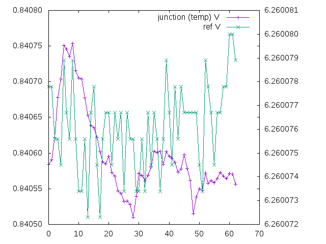
The lhs represents area of higher temperature, and the rhs lower temperature. At startup, the temperature rises and the voltage increases. At a certain temperature the tempco (mV/C) of the forward biased zener is balanced by the tempco of the reversed biased zener, and a local vertex is reached. After a small retracement, there appears to be another unknown secondary affect and curve. The trace eventually converges on the regulation temperature/voltage.


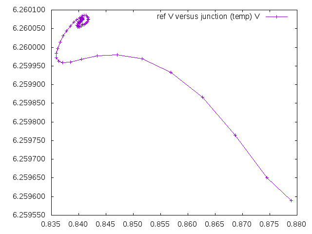
Skipping the first startup observations, provides a higher resolution view on the y axis. The plot shows output voltage varying by 8uV over the course of approximately 15 minutes.

Conditions involve an open room, exposed breadboard, high-ambient temperatures over 30C, circulating air currents, and 7 digit values from the 6.5digit rated data-acquisition unit. Additionally the circuit uses only two precision resistors - the resistors for the op-amps are inexpensive 1/4watt and not tempco rated.


The following users thanked this post: edavid

Offline Kleinstein

  • Super Contributor
  • ***
  • Posts: 14172
  • Country: de
Re: Ultra Low Noise Reference 2DW232, 2DW233, 2DW23x
« Reply #344 on: January 08, 2017, 11:50:20 am »
This an interesting way of plotting the data, but quite nice.

There seems to be more than just temperature that is influencing the temperature. I think this could be some delayed effects like creep in epoxy or thermal gradients and thermal EMF at the contacts. During turn on also the current source could contribute.

For the curve shown, the temperature (or current) chosen seems to be a little higher than the optimum. There is still quite some TC (e.g. 5 ppm/K range) in the last phase. A more accurate adjustment of the current or temperature to find the point where TC crosses zero might need a slower, more regulated temperature change (e.g. modulation of the set point of the temperature stabilization).
 

Offline julian1

  • Frequent Contributor
  • **
  • Posts: 731
  • Country: au
Re: Ultra Low Noise Reference 2DW232, 2DW233, 2DW23x
« Reply #345 on: January 09, 2017, 06:57:17 am »
... influencing the temperature. I think this could be some delayed effects like creep in epoxy or thermal gradients and thermal EMF at the contacts. During turn on also the current source could contribute.

Yes, I suspect some latent thermal effects. In the plots, the dw232 and board starts from ambient which is about 33C. It then climbs almost 30C to running temp. So there are heat gradients on the pcb and components. It would be better to get everything up to running temperature for 10 minutes, and then change the temperature setpoint -2, -1, 0 +1, +2 C and take the measurements.

Quote
For the curve shown, the temperature (or current) chosen seems to be a little higher than the optimum.

Yes, it's definitely slightly off. As good as I could get from stuffing about for 10 minutes.

Quote
e.g. modulation of the set point of the temperature stabilization.

Good point, the slope is near 0 around the vertex of the parabola which means that voltage is not as useful as the adjustment parameter. Dialing in operating temperature should provide more control.
 

Offline julian1

  • Frequent Contributor
  • **
  • Posts: 731
  • Country: au
Re: Ultra Low Noise Reference 2DW232, 2DW233, 2DW23x
« Reply #346 on: January 10, 2017, 08:13:45 am »
I changed the board around for a two op-amp design - after realizing that the reversed-bias zener would do equally well for on-die temperature regulation compared with the forward-biased one.


Some more test data,

Plot of a cold start. The operating temperature setpoint has been more finely adjusted to be closer to the balanced tempco vertex.


A plot of a longer run over the course of about 18 hours, shows that output is stronly correlated with ambient temperature. Since the on-die temperature is now regulated to a high degree - suspicion must be on other board components.


The linear relationship is clear when voltage change is plotted directly against ambient temperature. The output variation is around 40uV over 4 degrees.


40uV / 4C = 10uV/C, 10uV / 6.26V = 1.6ppm/C

The op-27 op-amps are rated at 0.2uV/C and probably do not contribute a lot to the variation.

However the Vishay trimpots are rated to +-10ppm/C.

Since these are needed for setting current and temperature, it is not clear how much further improvement is possible without entirely ovenizing the board.

I also wonder if the lm399 in the DAQ may have some contribution.
 

Offline Kleinstein

  • Super Contributor
  • ***
  • Posts: 14172
  • Country: de
Re: Ultra Low Noise Reference 2DW232, 2DW233, 2DW23x
« Reply #347 on: January 10, 2017, 12:21:48 pm »
The set point for the reference now looks much better: the slow final part looks more horizontal.

It somewhat depends on the surrounding circuit how much these parts influence the current. In the usual circuit 3 resistors that have an influence. But normally the influence should not be that large, as the zener resistance should be relatively large compared to the current setting resistor. To reduce the importance of the trimmer one usually combines it with fixed resistors to set the approximate value and thus have the trimmer only for a small adjustment.
The rather high current might be a problem here, as the zener resistance could include quite some substrate part and also the resistance of the pins and copper traces can get important.

There are also things like thermal stress to the resistors and the pins that might have an influence - so for a really high stability reference the cheap paper based boards are not ideal.

For a very stable system it might be worth to stabilize the temperature of a few more resistors as well, especially if you also need scaling to let's say 10 V. It might not be so much more effort to stabilize much of the circuit compared to only the chip itself.

The DAQ system could also contribute, though it might not be the LM399 ref used there, but other parts. The LM399 would definitely be a major part when is comes to noise. I would expect the noise level of the 2DW232 at something like 1/20 of the LM399.  So meaningful noise measurement would need something like a low frequency AC coupling and low noise amplification.
 

Offline Andreas

  • Super Contributor
  • ***
  • Posts: 3243
  • Country: de
Re: Ultra Low Noise Reference 2DW232, 2DW233, 2DW23x
« Reply #348 on: January 10, 2017, 10:29:20 pm »
Hello,

in the datasheets of other temperature compensated zeners (1N829A) the T.C. over current is given as "typical" curve (Figure 1):

http://www.microsemi.com/document-portal/doc_download/10940-sa6-3-pdf

my idea to measure was to measure those zeners pair-wise,
and keep the sum current constant.
So within a 1N829 pair I would set a temperature and then measure the one zener at 2mA .. 13mA and the other at 13 mA .. 2 mA (sum = 2 * 7.5 mA).
The idea is to keep the self heating constant.

with best regards

Andreas


Offline Kleinstein

  • Super Contributor
  • ***
  • Posts: 14172
  • Country: de
Re: Ultra Low Noise Reference 2DW232, 2DW233, 2DW23x
« Reply #349 on: January 11, 2017, 04:54:59 pm »
The 2DW232 has two zener diodes of about 5.3 V. So to use them as a compensated zener reference one uses one of the two in forward direction an the other as a zener diode.

From what a saw here so far, the TC seems to depend more on the current than with the 1N821 type diodes. A something like 1-2 mA the single diode is near zero TC and thus about -2 mV/k for the series connection, and at something like 15-30 mA the series connection has zero TC.

So keeping the sum of currents constant only works for just the zeners (e.g. 1-2 mA range).
For the series mode, it is the voltage of the single diode, that could be used to look at relative temperatures.
So it is plots like the ones from julian1 that give ref. voltage vs diode voltage.


Share me

Digg  Facebook  SlashDot  Delicious  Technorati  Twitter  Google  Yahoo
Smf