Author Topic: Ultra Precision Reference LTZ1000  (Read 1340399 times)

0 Members and 2 Guests are viewing this topic.

Offline mimmus78

  • Supporter
  • ****
  • Posts: 676
  • Country: it
Re: Ultra Precision Reference LTZ1000
« Reply #1975 on: November 20, 2017, 10:33:16 am »
3458A was set to fast NPLC, so it's hard to say. :)

No they say it's in 10 seconds aperture for the noise test ... the fast aperture was for checking INL.
 

Offline TiN

  • Super Contributor
  • ***
  • Posts: 4543
  • Country: ua
    • xDevs.com
Re: Ultra Precision Reference LTZ1000
« Reply #1976 on: November 20, 2017, 10:34:26 am »
No, 10 seconds was window aperture to capture 0.1Hz-10Hz noise.
There is no 10 second aperture in 3458A :)
YouTube | Metrology IRC Chat room | Let's share T&M documentation? Upload! No upload limits for firmwares, photos, files.
 

Offline mimmus78

  • Supporter
  • ****
  • Posts: 676
  • Country: it
Re: Ultra Precision Reference LTZ1000
« Reply #1977 on: November 20, 2017, 01:04:25 pm »
I think we are trying to say the same thing.
They say 10 seconds ... so it should be 600 (or 500) NPLC.
 

Offline TiN

  • Super Contributor
  • ***
  • Posts: 4543
  • Country: ua
    • xDevs.com
Re: Ultra Precision Reference LTZ1000
« Reply #1978 on: November 20, 2017, 02:05:53 pm »
Then you will get one sample, from which there is zero information about noise.
What they say is aperture of the sampling window was defined as 10 seconds worth of samples (whatever it was, NPLC1 or 10, etc).
So we are talking about different concept.
YouTube | Metrology IRC Chat room | Let's share T&M documentation? Upload! No upload limits for firmwares, photos, files.
 
The following users thanked this post: bopcph

Offline bopcph

  • Contributor
  • Posts: 14
  • Country: dk
Re: Ultra Precision Reference LTZ1000
« Reply #1979 on: November 20, 2017, 05:05:53 pm »
I would say that 60 sec. is absolute minimum if you want to measure down to 0.1 Hz
 

Offline Kleinstein

  • Super Contributor
  • ***
  • Posts: 14165
  • Country: de
Re: Ultra Precision Reference LTZ1000
« Reply #1980 on: November 20, 2017, 07:35:02 pm »
To get the 0.1 Hz to 10 Hz peak to peak noise, the closest thing would be sampling with 10 Hz (thus likely 2 or 3 PLC with AZ active) and taking samples over a 10 s window. For more accurate values one needs to repeat and average the peak to peak values. Alternative would be using something like 1 PLC sampling for a longer time (e.g. 60 s) and than get the noise spectrum and calculate the peak to peak value from the spectrum - this may not correctly care for popcorn noise however.

To get little noise from the references used the noise test is likely at about 0 output. This also allows to use the 100 mV range of the DMM to get low noise from there.
 

Offline Andreas

  • Super Contributor
  • ***
  • Posts: 3241
  • Country: de
Re: Ultra Precision Reference LTZ1000
« Reply #1981 on: November 20, 2017, 08:11:34 pm »
Hello,

For noise testing you will need a low noise amplifier to get out of the DMM noise.
And a 10 Hz sampling is by far not enough from Shannon theorem for a 10 Hz bandwidth.

So the best is usually a factor 10000 amplifier and a medium sensitive scope (2 mV/div)

with best regards

Andreas
 

Offline mimmus78

  • Supporter
  • ****
  • Posts: 676
  • Country: it
Re: Ultra Precision Reference LTZ1000
« Reply #1982 on: November 21, 2017, 09:35:37 am »
Kleinstein: yes it seems they used 1NPLC.
The chart (seems to) have a span of 10.5 seconds (cannot read it) ... and in the upper corner there is printed "105 samples" so this round up to 1NPLC.
Never though you can run the ADC at 0V to zero out noise of the references.
« Last Edit: November 21, 2017, 09:38:46 am by mimmus78 »
 

Offline kj7e

  • Frequent Contributor
  • **
  • Posts: 911
  • Country: us
  • Damon Stewart
Re: Ultra Precision Reference LTZ1000
« Reply #1983 on: November 28, 2017, 11:11:23 pm »
Question regarding the 400K temperature compensation resistor and use on the LTZ1000A.   I know this part is said not to be used or needed for the A part, but if used will it or could it cause any long term harm?  Reason I'm asking, I found both of my LTZ1000A's KX boards have negative T/C, #1 is about -0.08ppm/K and #2 is about 0.1ppm/K.  I found by using a 390K TC resistor on the #2 reference the TC is below 0.05ppm/K now.  10 to 40deg C test only drifted down 8uV.  That's just under 0.04ppm/K.  So I'm really inclined to  leave it in now.  Started with 1M, then 470K, then 390K and each time seeing an improvement.
« Last Edit: November 28, 2017, 11:13:25 pm by kj7e »
 

Offline kj7e

  • Frequent Contributor
  • **
  • Posts: 911
  • Country: us
  • Damon Stewart
Re: Ultra Precision Reference LTZ1000
« Reply #1984 on: November 29, 2017, 02:06:58 am »
Tried a 300K and ended up with the magic number.  I cant improve on this, not with the equipment I have.


I placed the reference in the refrigerator for a few hours to stabilize at 4.8 Deg C, started my plot when it warmed up to 5.0 Deg C, I let it warm up slowly at first, until about 18 Deg C, then turned on the oven to warm the internal temp to 39.6 Deg C (maxed out, normally set to 35.0).  I cant see any real change now, + or - 2.5uV is within the noise of the 34465a.


The 34465A is null'd at 7.161554v, 10 NLPC, 10v manual range, 10M input Z, math averaging 50 readings (med filter).  Hack or not I'm a happy camper now. Going to let it cook here overnight and see how it holds, then repeat the temp cycle in reverse tomorrow.
« Last Edit: November 29, 2017, 02:15:35 am by kj7e »
 

Offline martinr33

  • Frequent Contributor
  • **
  • Posts: 363
  • Country: us
Re: Ultra Precision Reference LTZ1000
« Reply #1985 on: November 29, 2017, 05:14:15 am »
That sure is interesting.

My initial hypothesis is that the temperature coefficient of the 390k resistor is offsetting the net temperature coefficient of the other sensitive resistors in the circuit. That's an interesting technique that could give a DMM better temperature stability. Also suggests that the temperature coefficient of the resistor is more important than the value, although your testing indicates a sensible progression.
 

Offline Andreas

  • Super Contributor
  • ***
  • Posts: 3241
  • Country: de
Re: Ultra Precision Reference LTZ1000
« Reply #1986 on: November 29, 2017, 07:33:07 am »
for improper PC layout (in the area of ground currents).

I would not sign that: even with the same layout I had a initial stray between +0.015 and -0.23 ppm with different LTZ1000A references.
Lead length of the LTZ1000A also plays a role if you look somewhat earlier in the thread.

What I finde somewhat strange: I could only increase the T.C. value with the resistor. (from negative to positive).
Perhaps you should make another measurement with 2 references and measuring the difference in 100mV range.

With best regards

Andreas
 

Offline hwj-d

  • Frequent Contributor
  • **
  • Posts: 676
  • Country: de
  • save the children - chase the cabal
Re: Ultra Precision Reference LTZ1000
« Reply #1987 on: November 29, 2017, 08:50:53 am »
I cant see any real change now, + or - 2.5uV is within the noise of the 34465a.

Then, you don't need your oven anymore?  ;D
 

Offline AG7CK

  • Regular Contributor
  • *
  • Posts: 131
  • Country: th
Re: Ultra Precision Reference LTZ1000
« Reply #1988 on: November 29, 2017, 11:58:06 am »
The 400k resistor is in the datasheet. So it does not imo sound credible to associate it primarily with PCB layout design considerations.

The datasheet reads on page 1: "LTZ1000A uses a proprietary die attach method to provide significantly higher thermal resistance than the LTZ1000".

I do believe this is the key to understanding why LT in the "7V Positive Reference Circuit" on page 7 writes that the 400k "PROVIDES TC COMPENSATION, DELETE FOR LTZ1000A".

Imo the 400k resistor is part of the "cybernetics" of the thermal-electrical control system that the LTZ1000 is.

My hypothesis is:

The primary control system of LTZ1000 is the oven. An equilibrium parameter (Vbe, left transistor) from this oven is transferred to the voltage reference circuit (Vbe, right transistor) via heat (yes - heat). [The two transistors are supposed to be "identical", and the ("received") Vbe of the right transistor is the main control parameter of the reference).]

Due to leakage or for some other reason, [my guess is that] this transfer can be improved on by introducing an electrical current transfer from the heater voltage at point (1) via the 400k resistor to R1 (which is part of the reference setting circuit). So an element of electrical control is added to the heat flow control (for the lower thermal resistance LTZ1000 only. For the LTZ1000A they seemingly has found that it is not needed).

This would also explain why Andreas could only tweak the TC more positive: Current flows from the heater positive side point(1) to R1 - and the higher the oven heater voltage, the higher the current.

I will try to upload a figure, and then edit the post if I find it necessary. I think there are several smart people here that soon will elaborate on this hypothesis or prove me wrong.
 

Offline Kleinstein

  • Super Contributor
  • ***
  • Posts: 14165
  • Country: de
Re: Ultra Precision Reference LTZ1000
« Reply #1989 on: November 29, 2017, 02:47:07 pm »
The 400 K resistor is a first approximation to compensate the residual TC of a typical LTZ1000 (non A) circuit. I don't think there is a really deeper thought behind it, just a way to do a small adjustment of the TC towards a more positive value. Depending on the actual reference, layout, thermal setup and temperature range a value different from 400 K (e.g. 270 K to 1 M) might be better. The TC of the resistor is not at all important, that would be only second order may be reducing the curvature if an PTC is used.

Andrea's measurements also showed that the contribution from the 400 K resistor is nonlinear, as it is following the heater voltage and thus about the square root of the heater power. So compensation is really good only for a small temperature range.

The A version seem to give lowet TC without the compensation and thus does not need the extra resistor. If the TC turns out to be too negative it can still be used, but it would be a surprise if 400 K turns out to be the right values. I would more expect higher values.
 

Offline kj7e

  • Frequent Contributor
  • **
  • Posts: 911
  • Country: us
  • Damon Stewart
Re: Ultra Precision Reference LTZ1000
« Reply #1990 on: November 29, 2017, 02:50:01 pm »
I cant see any real change now, + or - 2.5uV is within the noise of the 34465a.

Then, you don't need your oven anymore?  ;D

Not so much for the LTZ, but I'm also going to have a 10v buffer placed in the oven as well.  Even though I have a custom VHD200 network coming for the 10v buffer which should also minimize temp sensitivity, I want to keep everything temp stable ;D

I have been fighting the negative TC with my two references for months.  At first I thought it may be the lead length as I placed the LTZ1000A about 1.5mm above the board, but unlike for Andreas, dropping it to the board and trimming the leads did nothing for me.  Now I am very satisfied, Ill post the overnight plot and a reverse (from 40 Deg C to 15 Deg C ) plot a bit later today. 
« Last Edit: November 29, 2017, 02:52:52 pm by kj7e »
 
The following users thanked this post: hwj-d

Offline mimmus78

  • Supporter
  • ****
  • Posts: 676
  • Country: it
Re: Ultra Precision Reference LTZ1000
« Reply #1991 on: November 29, 2017, 03:17:54 pm »
The 400k resistor is in the datasheet. So it does not imo sound credible to associate it primarily with PCB layout design considerations.

The datasheet reads on page 1: "LTZ1000A uses a proprietary die attach method to provide significantly higher thermal resistance than the LTZ1000".

I do believe this is the key to understanding why LT in the "7V Positive Reference Circuit" on page 7 writes that the 400k "PROVIDES TC COMPENSATION, DELETE FOR LTZ1000A".

Imo the 400k resistor is part of the "cybernetics" of the thermal-electrical control system that the LTZ1000 is.

My hypothesis is:

The primary control system of LTZ1000 is the oven. An equilibrium parameter (Vbe, left transistor) from this oven is transferred to the voltage reference circuit (Vbe, right transistor) via heat (yes - heat). [The two transistors are supposed to be "identical", and the ("received") Vbe of the right transistor is the main control parameter of the reference).]

Due to leakage or for some other reason, [my guess is that] this transfer can be improved on by introducing an electrical current transfer from the heater voltage at point (1) via the 400k resistor to R1 (which is part of the reference setting circuit). So an element of electrical control is added to the heat flow control (for the lower thermal resistance LTZ1000 only. For the LTZ1000A they seemingly has found that it is not needed).

This would also explain why Andreas could only tweak the TC more positive: Current flows from the heater positive side point(1) to R1 - and the higher the oven heater voltage, the higher the current.

I will try to upload a figure, and then edit the post if I find it necessary. I think there are several smart people here that soon will elaborate on this hypothesis or prove me wrong.
Nice ... this call for an experiment.

I expect TC to diminish when the "ambient" temperature is very near to the regulation limit.

The less power is needed to heat the reference die, the less gradient there will be, the lesser TC it will have.

It will be helpful to put on a chart, heater power used and "ambient temperature" with reference V delta (or calculated TC).
« Last Edit: November 29, 2017, 03:20:27 pm by mimmus78 »
 

Offline kj7e

  • Frequent Contributor
  • **
  • Posts: 911
  • Country: us
  • Damon Stewart
Re: Ultra Precision Reference LTZ1000
« Reply #1992 on: November 30, 2017, 01:27:23 am »
Turned the oven off and put some frozen cool packs on the reference enclosure, plot from 39.6 Deg C to 12.8 Deg C internal oven temp, I cant detect any noticeable TC drift with the LTZ1000A now.  Before adding the 300K tempco resistor I saw a very pronounced negative TC and it was 100% repeatable.  The very slight downward drift over 5 hours here is the 34465A as the room warmed up slightly.  The 34465A will drift downward several uV per Deg C increase.  The slight fluctuations where mostly caused by me moving around close by and disturbing the air around the meter.  Id say its darn near flat from 5 to 40 Deg C.  Its now beyond my capability to measure.


The 34465A is null'd at 7.161552v, 10 NLPC, 10v manual range, 10M input Z, math averaging 10 readings (fast filter).

« Last Edit: November 30, 2017, 01:31:08 am by kj7e »
 

Offline TiN

  • Super Contributor
  • ***
  • Posts: 4543
  • Country: ua
    • xDevs.com
Re: Ultra Precision Reference LTZ1000
« Reply #1993 on: November 30, 2017, 04:49:03 am »
...
Imo the 400k resistor is part of the "cybernetics" of the thermal-electrical control system that the LTZ1000 is.
...
Nice ... this call for an experiment.
...

Well, off you go.

Ask and you shall receive :) Here are three test results of my latest FX LTZ1000A reference, which follows the datasheet schematics with LT1013ACN.


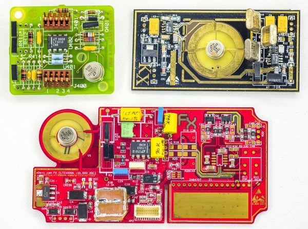
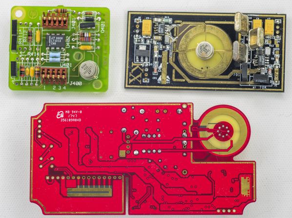
Setup of DUT (not the sample shown on photo above): LTZ1000ACH, 51 week 2016, 1K AE XB BMF, 15K AE XB BMF, two S102 in parallel to get 132R.
Third unit module running tempco test, graceful ramp +20c to +50c, with help of Keithley 2510 and YSI 44006.

LTZ section powered from +11V, sourced by low-noise LT3042 LDO. Input power delivered from Keithley 2400, set at +12V with 105mA compliance.

Output measured by three meters, pair of 3458A and Keithley 2002 (GPIB 4).


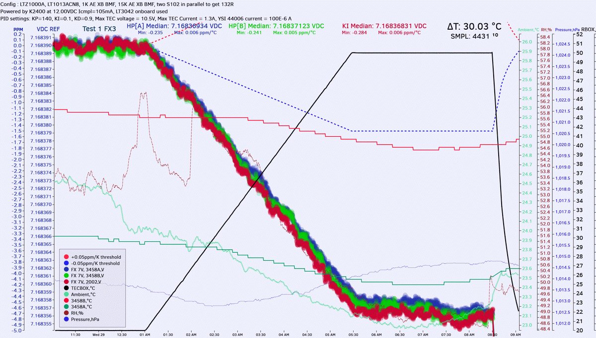
This module provided initial TC -0.25 ppm/K. No compensation resistor populated (R13 position).

For Test 2 additional compensation resistor was added, 390KΩ 5% 1206 on R13 position.


Much better now!

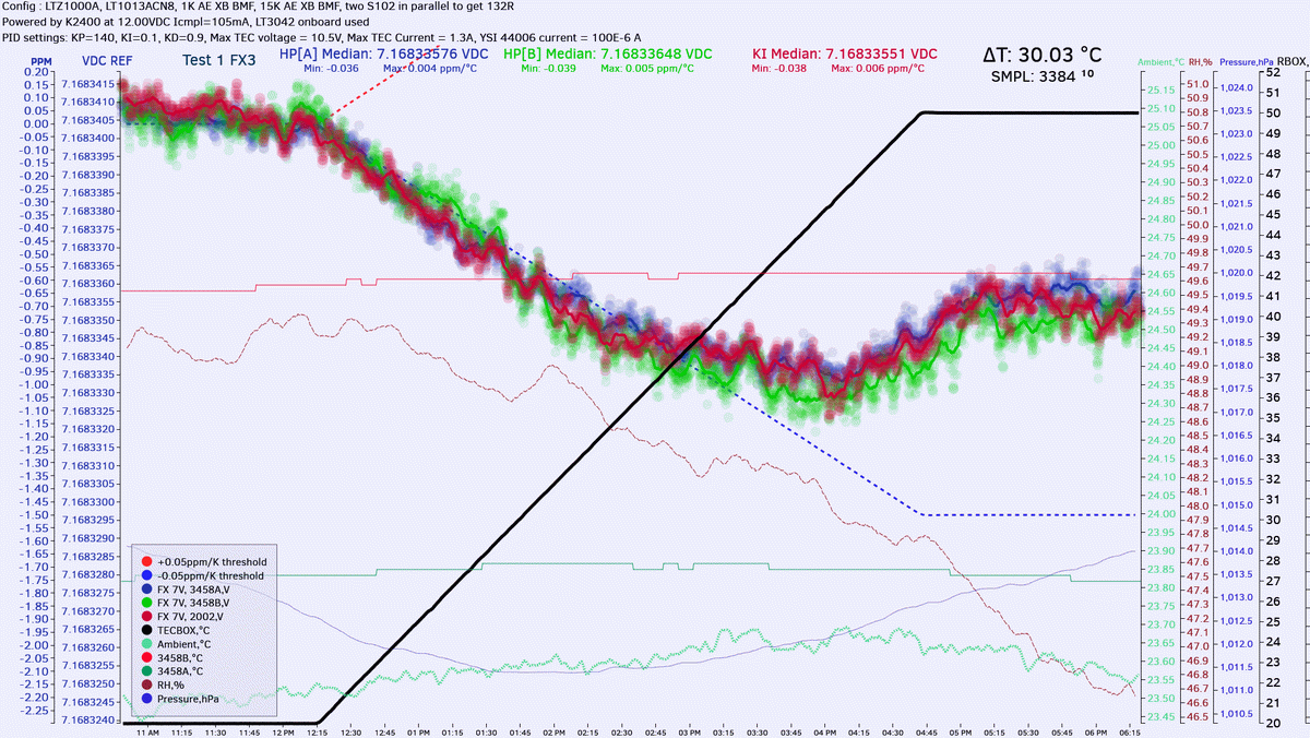
Retest with 331KΩ R13 resistor:


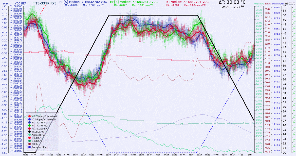
If judge by temperature ramp down curve, then tempco is <0.02ppm/K with this resistor setup. (0.5 ppm change over 25K delta).
Pay attention on the left ppm vertical scale of the graphs, it's not the same between the tests.

Also this is non-aged reference, 0 hours burn-in. I started TC test first thing after assembly.

CSV-file with all data for those who want to play with own plotting/analysis.

As bonus, one can see the 2002 noise performance (20 NPLC, default DFILTER 10 ON, LINE SYNC) compared to 3458A (NPLC100)  :-DMM
YouTube | Metrology IRC Chat room | Let's share T&M documentation? Upload! No upload limits for firmwares, photos, files.
 
The following users thanked this post: kj7e

Offline Kleinstein

  • Super Contributor
  • ***
  • Posts: 14165
  • Country: de
Re: Ultra Precision Reference LTZ1000
« Reply #1994 on: November 30, 2017, 04:36:13 pm »
The measured TC of TiNs reference looks rather constant, thus a nearly perfect linear temperature - voltage relation. The compensation however is nonlinear as the heater voltage is about proportional to the square root of the heater power and thus the square root of set temperature minus actual temperature minus self heating. One can see the rather curved relationship with the compensation resistor. At high temperatures the compensation has too much effect. I wonder if it might be wort using a different type of TC compensation, that is more linear. I first idea might be a PT1000/PT100 in series to R2, maybe with a second resistor in parallel to reduce/adjust the strength.
 

Offline mimmus78

  • Supporter
  • ****
  • Posts: 676
  • Country: it
Re: Ultra Precision Reference LTZ1000
« Reply #1995 on: November 30, 2017, 05:27:39 pm »
Well yes initial TC is linear ... but this is the LTZ1000A not the LTZ1000.
Still convinced that LTZ1000 operated at near temperature regulation limit should exhibit less TC ... maybe I check this, this night.
 

Offline kj7e

  • Frequent Contributor
  • **
  • Posts: 911
  • Country: us
  • Damon Stewart
Re: Ultra Precision Reference LTZ1000
« Reply #1996 on: December 01, 2017, 12:34:44 am »
for improper PC layout (in the area of ground currents).

I would not sign that: even with the same layout I had a initial stray between +0.015 and -0.23 ppm with different LTZ1000A references.
Lead length of the LTZ1000A also plays a role if you look somewhat earlier in the thread.

What I finde somewhat strange: I could only increase the T.C. value with the resistor. (from negative to positive).
Perhaps you should make another measurement with 2 references and measuring the difference in 100mV range.

With best regards

Andreas

Done, used my second LTZ1000A KX ref to null the DUT, this left ~20mV to null in the 3465A.  Used 100mV range, 100NLPC with math filter set to fast (10 readings), AZ on and 10M Ohm Z. Sweep from 10.6 deg C to 40.0 deg C shows less than 2.5uV deviation or ~0.35ppm.  There is no real curve or slope, its seems to average right down the middle, no non-linearity seen.  So over a 29.6 deg span that comes to ~0.01ppm? It appears to be simply flat across any temp I would ever expect this box to be used in.  Maybe I need to send this one over to TiN for better testing.


Offline mimmus78

  • Supporter
  • ****
  • Posts: 676
  • Country: it
Re: Ultra Precision Reference LTZ1000
« Reply #1997 on: December 01, 2017, 12:35:24 am »
So I run my tests with my heated LTZ1000 (non A - no compensation).
Results are opposite to what I expected, than more I approach the upper limit of the heater, than more TC increase in a non linear way.
I have to think at this.


VOUT        T       TC
========    ==     ====
7.0880010   25   
7.0880035   30     0.07
7.0880065   35     0.08
7.0880115   40     0.14
7.0880155   42.3   0.24
7.0880175   43.3   0.28
7.0880210   44.4   0.45


« Last Edit: December 01, 2017, 12:38:16 am by mimmus78 »
 

Offline TiN

  • Super Contributor
  • ***
  • Posts: 4543
  • Country: ua
    • xDevs.com
Re: Ultra Precision Reference LTZ1000
« Reply #1998 on: December 01, 2017, 04:57:36 am »
Thermographs of the FX reference, LTZ1000A with 1K/15K setpoint, powered by +11VDC. Large size clickable.  :-DMM

YouTube | Metrology IRC Chat room | Let's share T&M documentation? Upload! No upload limits for firmwares, photos, files.
 
The following users thanked this post: chickenHeadKnob

Offline Andreas

  • Super Contributor
  • ***
  • Posts: 3241
  • Country: de
Re: Ultra Precision Reference LTZ1000
« Reply #1999 on: December 01, 2017, 07:52:29 am »
  There is no real curve or slope, its seems to average right down the middle, no non-linearity seen.  So over a 29.6 deg span that comes to ~0.01ppm? It appears to be simply flat across any temp I would ever expect this box to be used in. 

Hello,

seems to be only noise (perhaps by thermal EMF).
Did you cover your inputs to the DMM with a cloth?

with best regards

Andreas


Share me

Digg  Facebook  SlashDot  Delicious  Technorati  Twitter  Google  Yahoo
Smf