Dr.Frank,
I will take bank apart once I get back Taiwan next week, and will list all configurations (opamps, resistors, LTZ type) per each channel. Two of KX modules are with AUGAT socket for zener.
 martinr33
, my 3458As have no measureable tempco, but before you go into gossip theory, do not forget that all references are connected to meter thru scanner card, NOT directly. And I did not measure impact of the scanner JFETs on tempco/drift yet

Also all modules, except A9 had thermal stress at start from wiring connections (not using any connectors at KX outputs, only direct solder copper twisted pairs between scanner and board). FX 10V modules had zero aging at all, with fresh LTZ chips.
I periodically was checking drift and stability of the meter, it's still accurate and stable. In fact, just before leaving to vacation, I had calibrated two KX LTZ1000CH's refs from CalMachine and shipped to him.
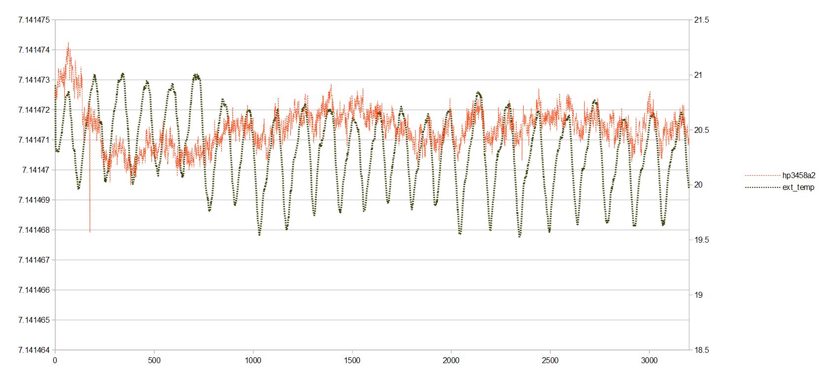
Assigned value: KX1 module (large input power binding posts):
7.141467 VDC ,
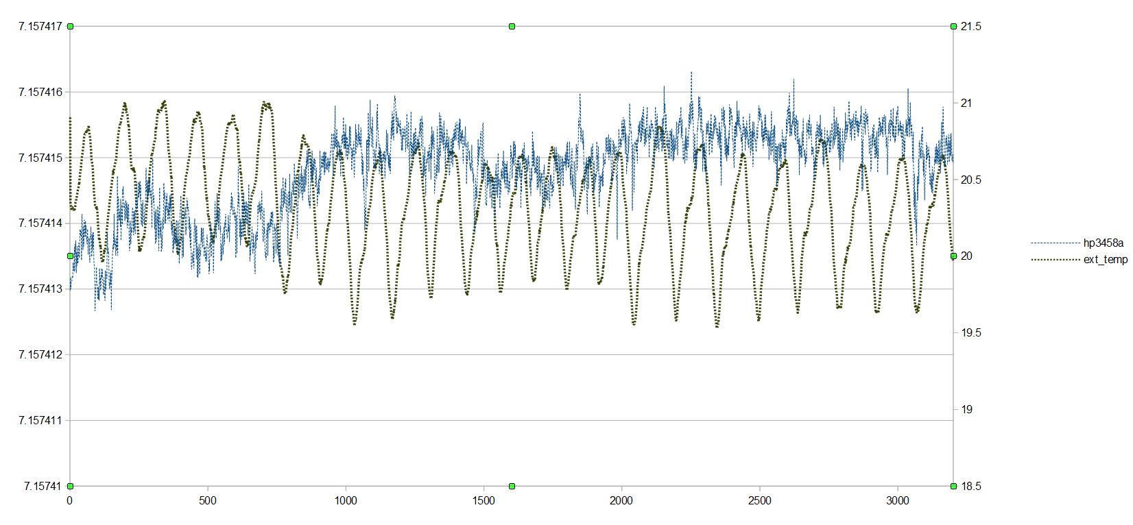
https://xdevs.com/ckx1_test5_tc/Assigned value: KX2 module (smaller input power binding posts):
7.157411 VDC ,
https://xdevs.com/ckx2_test10_tc/ These modules arrived to CalMachine, but since he's too
lazy shy busy, he just got few hours on each module, using his calibrated (i think <30 days ago) 3458A. Here is his data:
CSV-data.
Plots:
So output deviation fits my expectation of 2ppm DCV at my lab accuracy, with good margin:
KX1 module
7.157411 VDC (xDevs lab) vs 7.157415 VDC (CalMachine lab), +0.56 ppm off.KX2 module
7.141467 VDC (xDevs lab) vs 7.141472 VDC (CalMachine lab), +0.70 ppm off.Not that bad, given international air shipping in winter and different calibration source (my 3458As calibrated vs 732B (cal August 2016 by Tektronix USA) in January/February 2017). CalMachine's meter calibrated by Keysight.
Also CalMachine's temp is lower, I calibrated values at +24C, not 20. So tempco may contribute another 0.2ppm error.


 Topic: Ultra Precision Reference LTZ1000 (Read 1344963 times)