Author Topic: Nanovolt scanner card teardown, Keithley 7168 and it's use for resistor logging  (Read 15656 times)

0 Members and 1 Guest are viewing this topic.

Offline lukier

  • Supporter
  • ****
  • Posts: 634
  • Country: pl
    • Homepage
Re: Teardown of nanovolt scanner card, Keithley 7168
« Reply #25 on: February 04, 2017, 08:10:58 pm »
Today's photos...

Hmm that's not CSA7404  :D. Is there an exciting repair story associated with this new Tek? :)
 

Offline TiNTopic starter

  • Super Contributor
  • ***
  • Posts: 4543
  • Country: ua
    • xDevs.com
Re: Teardown of nanovolt scanner card, Keithley 7168
« Reply #26 on: February 04, 2017, 08:34:21 pm »
Nope, it's boring brand new. Borrowed for some other tests.
YouTube | Metrology IRC Chat room | Let's share T&M documentation? Upload! No upload limits for firmwares, photos, files.
 

Offline TiNTopic starter

  • Super Contributor
  • ***
  • Posts: 4543
  • Country: ua
    • xDevs.com
Re: Teardown of nanovolt scanner card, Keithley 7168
« Reply #27 on: February 07, 2017, 04:22:04 am »
First data bodges came in! :)
8K samples using K7168 card, A10 (A=100K) and K2002.

nvs1.png is data as is, 1000 samples per channel.
nvs1_ofs.png is same dataset, but with offsets removed via math.

Copper short is directly on card channels terminals. Card was NOT cleaned/serviced. So that's next step, clean all copper surfaces, make fresh shorts, and retest again.  ;)
Channels 5,6,7,8 already look decent even with condition as is.
YouTube | Metrology IRC Chat room | Let's share T&M documentation? Upload! No upload limits for firmwares, photos, files.
 

Offline TiNTopic starter

  • Super Contributor
  • ***
  • Posts: 4543
  • Country: ua
    • xDevs.com
Re: Teardown of nanovolt scanner card, Keithley 7168
« Reply #28 on: February 14, 2017, 04:23:15 am »
First usage case of Keithley 7168 just about to get proof. As some followers might discover, I recently snagged nice stash of 60+ pcs Vishay BMF resistors, all of which would be cool to test for tempco.
If I'd do that using two 8.5-digit meters and nV-meter+current source, that will take..

30 hours for one run, 3 resistors at at time (2002+2002+182M) = 20 runs * 30 hours/each = 600 hours + setup time. That's 25+ days of testing.  :o
111 hours for one run, 10 resistors at a time (2002+2002+182M+7168) = 6 runs * 111 hours/each = 666 hours + setup time. 27 days of testing  :rant: :scared:

Perhaps I could optimize delays/settings a bit to run scanner setup bit quicker.

Setup for regular DMMs is simple: Keithley 2002 U1 measures 1 x VPG102L 40.000 K? #2 BMFR, 200K range, OCOMP OFF, Keithley 2002 U2 measures 1 x VPG102L 40.000 K? #1 BMFR, 200K range, OCOMP OFF, same.

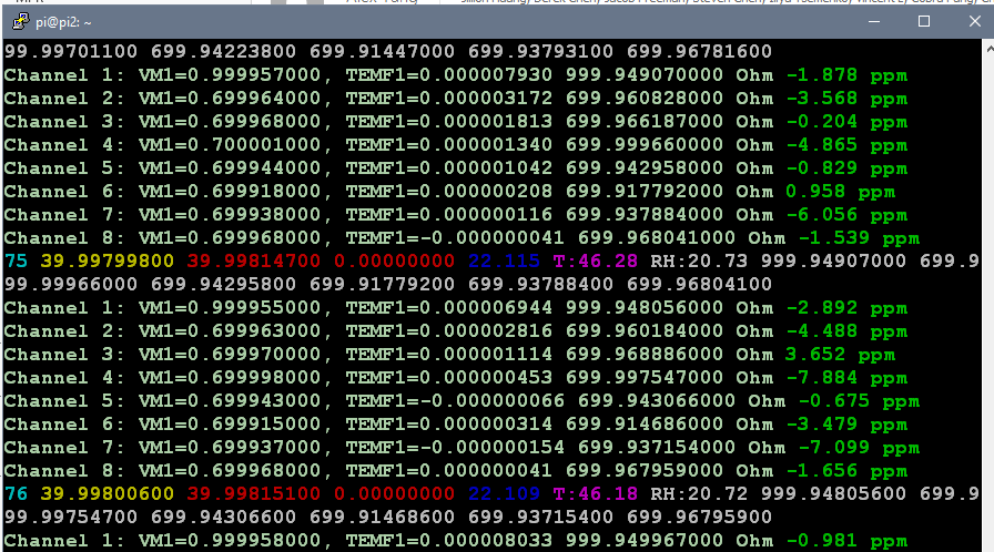
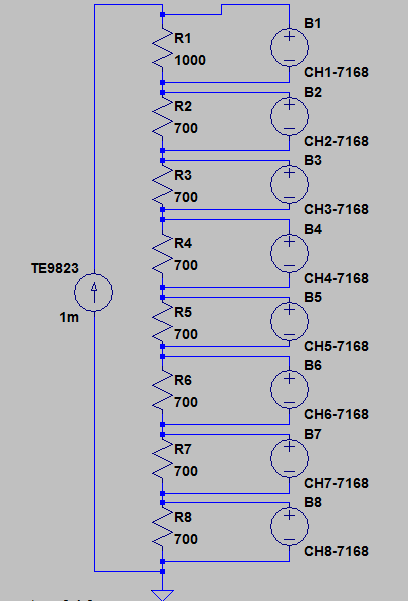
Resistor test using scanner is bit different, using Time Electronics 9823 MFC to source stable 1.00000 mADC (confirmed by 3458A) to chain of 8 resistors (AE 1K? + S102 700? + S102 700? + S102 700? + S102 700? + S102 700? + S102 700? + S102 700?). Keithley 7168 8-channel nanovolt scanner + RPI in K7001 chassis scanning voltage across each resistor in chain, using Kelvin connection. Resistors are tied to copper foil to keep their temperature gradients equal. After each reading with current Keithley 182-M measures voltage across resistor, then MFC source 0.00000 mADC current and voltmeter reads TEMF compensation voltage to calculate offset compensated OHM. Formula for resulting R simply equal V_curr_on - V_curr_off / 1E-3 mA.

Then resulting DSV-log uploaded to my server, from which on special page my ugly D3.js Javascript contraption cooks rainbow-monster graph. Deviation shown in ppm/reference, with reference values for each channel used as:

Code: [Select]
var ref_ch1    = 999.951202;           // 7168 CH1
var ref_ch2    = 699.960845;           // 7168 CH2
var ref_ch3    = 699.966292;           // 7168 CH3
var ref_ch4    = 699.997901;           // 7168 CH4
var ref_ch5    = 699.941758;           // 7168 CH5
var ref_ch6    = 699.913797;           // 7168 CH6
var ref_ch7    = 699.938197;           // 7168 CH7
var ref_ch8    = 699.968415;           // 7168 CH8
var ref_k4     = 39998.171;            // 2002 4
var ref_k6     = 39998.007;            // 2002 6

These are spot readings after 3 hours of 20.00C stable temperature in box. These are our "zero" points from which we calculate tempco.


Initial chart:
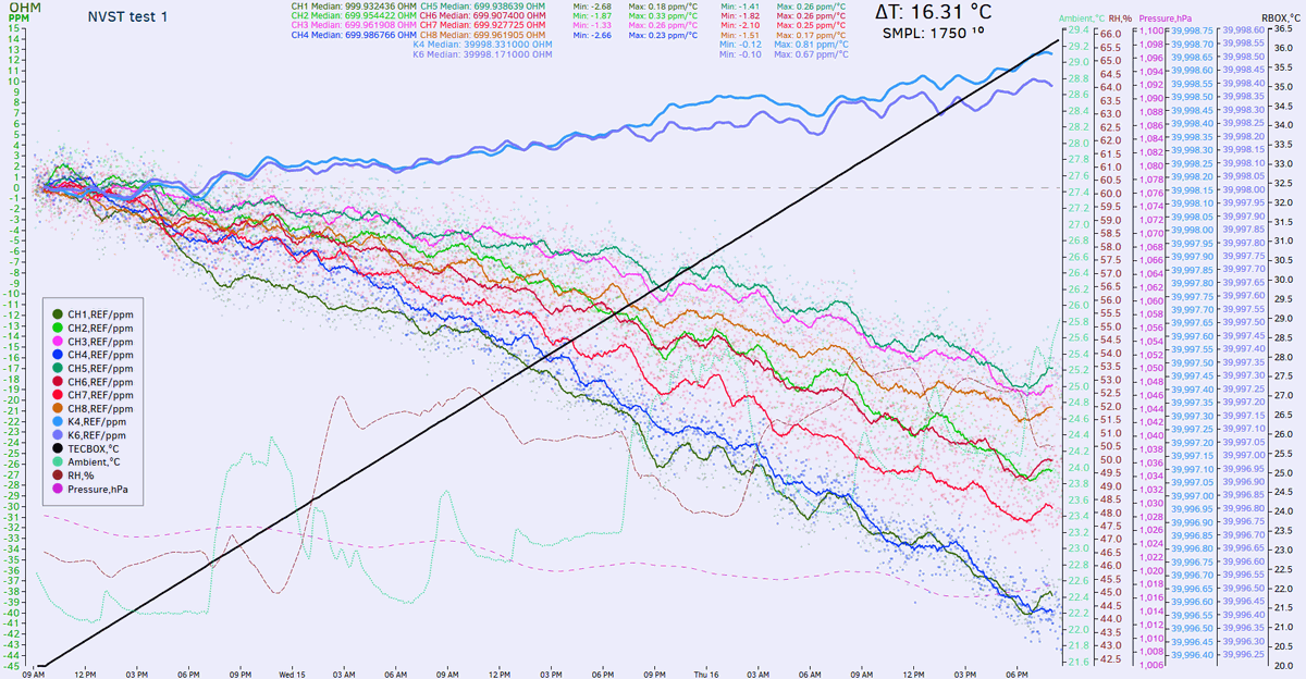


Script calculates min/max tempco for each channel as ppm / max temperature from 20C baseline. JS data on page is updated in realtime as data capture goes
Come back after 111 hours :)

« Last Edit: February 14, 2017, 04:40:57 am by TiN »
YouTube | Metrology IRC Chat room | Let's share T&M documentation? Upload! No upload limits for firmwares, photos, files.
 

Offline TiNTopic starter

  • Super Contributor
  • ***
  • Posts: 4543
  • Country: ua
    • xDevs.com
Slowly but surely data is coming thru. As one can see, all seven 700 Ohm S102 + 1K AE are linearly going down, having linear tempco around -1.2...-2.8ppm/K.
Pair of 40K hermetical VHP102L going little up (these two measured by direct 4W connection at own K2002's).


What i'm happy to see is no random non-linear stuff, so setup seem to be working as expected. I have few ideas try speed up next test from 110 hours to ~35 hours.
Right now current source is applied on each resistor on scanner card individually. Meaning it takes a lot of time, as there are 8 seconds to let current source and scanner switch to settle. Double that time, as two measurements taken to remove thermal EMF (one with 1mA current, second with 0mA current).

By moving current source control outside of switching cycles and doing 8 measurements with current source on, and then again 8 measurements with current source off might work as well, as it would be <10 seconds between compensation cycles and unlikely that thermal EMF change a lot in this time. I also will modify method a bit, to source +1mA and reversal -1mA instead of +1mA and zero current. Similar is done in TruOhm mode on Datron 1271/1281/8508A.

YouTube | Metrology IRC Chat room | Let's share T&M documentation? Upload! No upload limits for firmwares, photos, files.
 

Offline mimmus78

  • Supporter
  • ****
  • Posts: 676
  • Country: it
Hi guys,

I'd like to try to create a clone of this card for my lab. I was searching the most appropriate jfet for the purpose so I come to two possible options:

1. IFN5432
2. MMBF5434

The first is hard to find and costs a lot.
The second have an SMD package, a reasonable price and is easy to find.
I think SMD package can also help a little to control EMF.
Cons is that it have higher ON resistance.

Both JFET have higher Ron resistance and leakage than Keithley 7168 specification ... does anyone know better options for the purpose? 

Regards,

D.
 

Online Echo88

  • Frequent Contributor
  • **
  • Posts: 826
  • Country: de
I never could find a datasheet for the JFETs used in the K7168 and only know that they have copper pins. Would have to calculate the errors, but i dont think that leakage plays a role here/can be omitted by a suitable changed schematic?

If its just about RDSon i also can name the J105: http://pdf.datasheetcatalog.com/datasheet/vishay/70230.pdf

At the moment im building my voltage-reference-scanner based on PVA1054-OptoFETs (35R RDSon, 10GR Off-resistance, they also have copper-pins). According to my calculations the 35R and leakage dont matter when a 10G-input-DMM is used. Also my first tests with a Keithley 181 Nanovoltmeter showed <= 30nV error with these OptoFETs which is absolutely sufficient to me. I will post results when i finished building the scanner.
 
The following users thanked this post: mimmus78

Offline Kleinstein

  • Super Contributor
  • ***
  • Posts: 14195
  • Country: de
My guess is that leakage could be more of a problem than a slightly higher R_on. Also FETs that are good for 25 V might limit the useful range, as you still have to subtract the control voltage from that.

I would more consider something like J111 / MMBFJ111.
 
The following users thanked this post: mimmus78

Offline mimmus78

  • Supporter
  • ****
  • Posts: 676
  • Country: it
I never could find a datasheet for the JFETs used in the K7168 and only know that they have copper pins. Would have to calculate the errors, but i dont think that leakage plays a role here/can be omitted by a suitable changed schematic?

If its just about RDSon i also can name the J105: http://pdf.datasheetcatalog.com/datasheet/vishay/70230.pdf

At the moment im building my voltage-reference-scanner based on PVA1054-OptoFETs (35R RDSon, 10GR Off-resistance, they also have copper-pins). According to my calculations the 35R and leakage dont matter when a 10G-input-DMM is used. Also my first tests with a Keithley 181 Nanovoltmeter showed <= 30nV error with these OptoFETs which is absolutely sufficient to me. I will post results when i finished building the scanner.
30nV seems pretty good also to me ... Considering there is a led inside the thingy that will heat up the chip is even more exceptional.

Inviato dal mio ONEPLUS A5010 utilizzando Tapatalk
 

Offline mimmus78

  • Supporter
  • ****
  • Posts: 676
  • Country: it
I never could find a datasheet for the JFETs used in the K7168 and only know that they have copper pins. Would have to calculate the errors, but i dont think that leakage plays a role here/can be omitted by a suitable changed schematic?

If its just about RDSon i also can name the J105: http://pdf.datasheetcatalog.com/datasheet/vishay/70230.pdf

At the moment im building my voltage-reference-scanner based on PVA1054-OptoFETs (35R RDSon, 10GR Off-resistance, they also have copper-pins). According to my calculations the 35R and leakage dont matter when a 10G-input-DMM is used. Also my first tests with a Keithley 181 Nanovoltmeter showed <= 30nV error with these OptoFETs which is absolutely sufficient to me. I will post results when i finished building the scanner.
How do you know there are copper pin?

Inviato dal mio ONEPLUS A5010 utilizzando Tapatalk


Online Echo88

  • Frequent Contributor
  • **
  • Posts: 826
  • Country: de
I filed one pin down and tested it against a magnet, its copper. Apart from that the Datasheet claims <200nV offset voltage, so i think they couldnt use any other pin-metal.
 
The following users thanked this post: mimmus78

Offline Kleinstein

  • Super Contributor
  • ***
  • Posts: 14195
  • Country: de
I would not be worried so much about copper or steel pins, as the temperature gradients across the pins should be rather small and in addition the pins are about symmetric an would thus cancel to a large extend.

The more tricky part is the interface to the silicon here the Seebecke coefficient is much higher (around +-500 µV/K) for doped silicon.
The largest part of this will compensate, but a small asymmetry could be a problem.  With just a JFET, there will be very little heating and thus very little temperature gradients.
 

Offline acts238willy

  • Regular Contributor
  • *
  • Posts: 95
  • Country: us
Any idea where the 15V batteries can be found?
I want to clean mine up for a possible sale...
and right now, I have a pair of kit-bashed 2032 stacks.
 

Offline TiNTopic starter

  • Super Contributor
  • ***
  • Posts: 4543
  • Country: ua
    • xDevs.com
I don't know exact replacement, but I'll buy your card even w/o batteries.
YouTube | Metrology IRC Chat room | Let's share T&M documentation? Upload! No upload limits for firmwares, photos, files.
 

Offline TiNTopic starter

  • Super Contributor
  • ***
  • Posts: 4543
  • Country: ua
    • xDevs.com
Yay, got my 2nd card with bonus Keithley 7168-316 cable set.


For those who want to know, selected JFETs used in this card are matched PN5434's.
YouTube | Metrology IRC Chat room | Let's share T&M documentation? Upload! No upload limits for firmwares, photos, files.


Share me

Digg  Facebook  SlashDot  Delicious  Technorati  Twitter  Google  Yahoo
Smf