Alright, we getting there. Just bit of spaghetti-coding, and should be ready for first run tomorrow.
Suggestions what to test first are welcome!
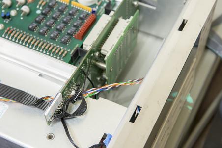
Today's photos... Just first checks on level translator bodge and testing code to control 7001 backplane serial drivers (UCN5841, latched 8bit driver).

One hour and channels are working fine..
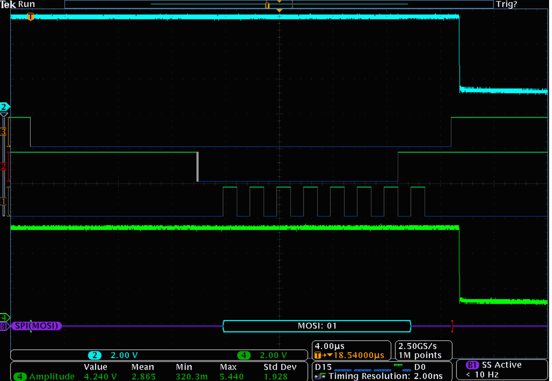
Channel ON:
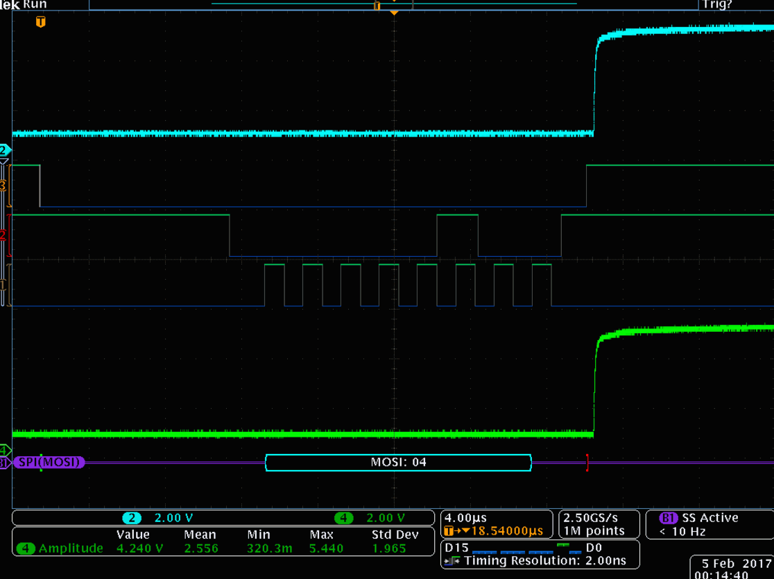
Channel OFF:
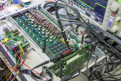
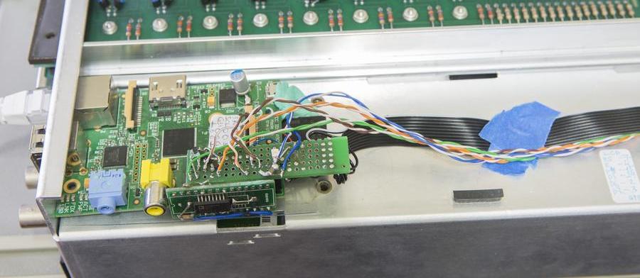
Wiring and rear Pi location:
Looks ugly, but should be good enough. I decided to deviate from my usual "design custom PCB, do weeks and weeks of testing" and just bodged one off thing which seem to work. Don't want this to turn into month-long project.
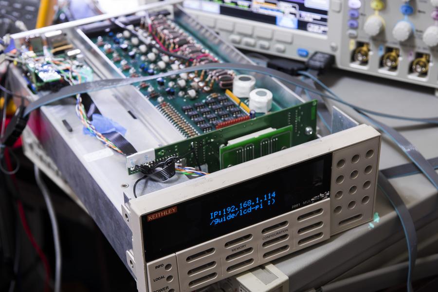
I don't have original 7001 front panel anymore (well, I have the board, but it has no VFD), so plonked 16x2 OLED instead to show status/IP/etc.