no doubt a thing that is not what it is purported to be, but ...
... but I have a closed-source 3d-printer device that handles three step-motors and it doesn't bark-report the X-Y-Z position to the operator, and it would be useful to know at which step of the gcode-model it has arrived during the process.
Due to dimension (and silly design of the engine) problems, I can't mount encoders

So, you have three bipolar step-motor, powered at 24V, and you can't hack the motherboard to extract the command line (that is TTL), you are after the driver, everything else is a black-box (literally).
It’s a common approach in the industrial world to micro-step a stepper motor to achieve better resolution in the system. The movement of the stepper motor is caused by exciting currents through the motor coils, and since the goal is to divide a full motor step into multiple micro-steps, the “how-to” part of the task is very straightforward – simply generate multiple current levels. This is the so-called “current regulation” in stepper motor controls.
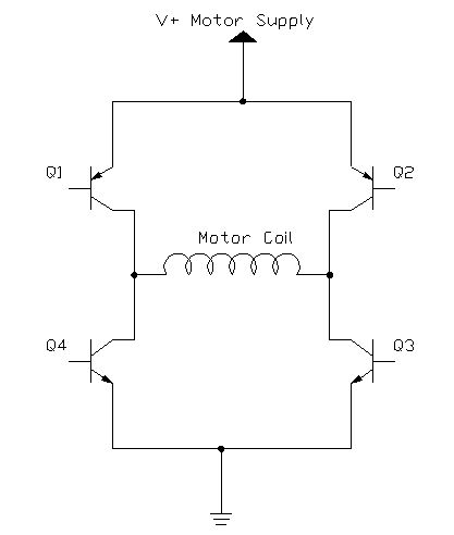
two H-briges are used to drive the motor, one bridge per coil
I do not know how the driver works internally, but probably
it applies PWM to the "V+motor supply" of the bridge in the fig.
Thus, on a pure logic level I can design a mini-CPLD module able to follow the microstepping increment/decrement (that means I can have a status array, {X,Y,Z}, to be queried on demand through a serial connection, from this CPLD to a .. say .. linux board), but I have some doubt about the physical interface, (how to sense the current?) and more specifically about HOW to extract this information on the driver side at coils: cause I can only access coils!
Trough a couple of Optoencoders per coil? Ummmm
Tips? Idea?


