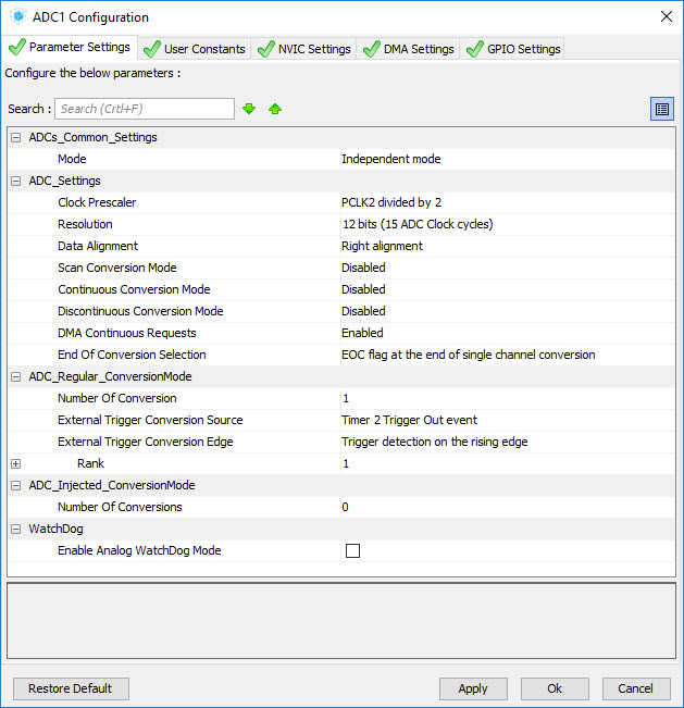
I have another problem also. I put the timer trigger on 100mS. it means it triggers its interrupt and ADC every 100mS. Below is the configuration of the ADC and Timer2.
I checked the TIM2 interrupt by a GPIO toggle and it gets fired every 100mS or 50Hz which is correct.
BUT the ADC DMA gets fired 2 times per second, it means 2Hz

. it is weird because I just put 100 for the buffer and whole sampling to fire the ADC DMA interrupt must not take more than 100 * 0.5uS = 50uS , because each ADC channel can handle the speed of 2Msps. This speed is correct if the ADC works in the continuous conversion mode, but I could not achieve this when I trigger it externally.

The triggering is slow and it should not make any timing conflict, it means the conversion finishes sooner before the next trigger comes in