Author Topic: Open Source Solar BMS (Old successful Kickstarter).  (Read 21807 times)

0 Members and 1 Guest are viewing this topic.

Offline electrodacusTopic starter

  • Super Contributor
  • ***
  • Posts: 1858
  • Country: ca
    • electrodacus
Open Source Solar BMS (Old successful Kickstarter).
« on: March 23, 2014, 06:26:35 pm »
I'm quite new on this forum but I will be here to stay if I like it :)

I'm not sure if this was the right category to list this or the one about Kickstarter projects.
Since this is both about Open Source HW and SW and will be on Kickstarter starting tomorrow.

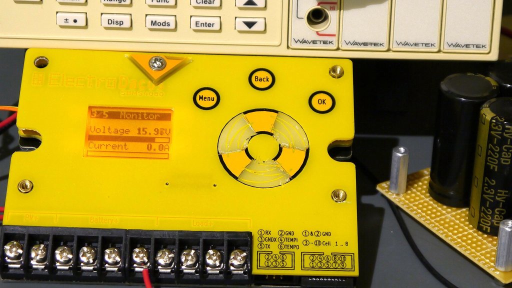
But let me give you a bit more details (not sure I'm allowed to post links or embed my youtube videos explaining this) so I will just insert a photo with a 3D render of my design (Is not just a 3D render there is already a working beta sample search on youtube for SBMS4080)
   
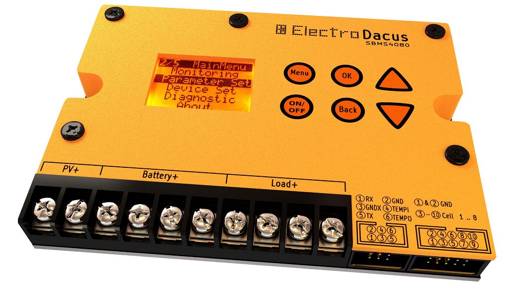
and the uglier beta sample :)

I have done this 3D render in Blender 3D it was an animation presentation video for Kickstarter until I found out that they do not allow 3D renders since people my confuse them with the real thing so I made a new one without the 3D render part for them.

But what is it ?
Is a Battery Management System (BMS) that can use solar PV panels to charge any type of Lithium batteries (3 up to 8 cells) or even Supercapacitors.
Of course it can use a constant current power supply instead of solar panels but the design started for my need of such a device. I live OffGrid and use LiFePO4 batteries to store energy produced by my solar panels.
I made the decision to make this fully open source both hardware and software so it can be a great learning platform for those that want to learn how to program microcontrollers (ARM cortex M0) in this case and also electronic design including PCB design using KiCad (Yes I'm an user of Open Source software myself for over 10 years)
If the stretch goal is achieved (I hope it is) then I will make detailed video tutorials explaining every aspect of HW and SW so it will be even more than just an Open Source project.

What I will like to know from you.
What do you think about this project ?
Is this the right part of the forum to have this discussion?
This will be my first Open Source HW project. If you have any experience how do I do that? are there more than one alternative?
There seems to be a lot of websites what is the right one ? or the best one to get that logo and license?
It will be Open Source the definition is not important since I will release everything that I have anyway. I just wanted to add the logo first on my PCB's   
« Last Edit: March 30, 2015, 01:53:14 am by electrodacus »
 

Offline electrodacusTopic starter

  • Super Contributor
  • ***
  • Posts: 1858
  • Country: ca
    • electrodacus
Re: Open Source Solar BMS development board.
« Reply #1 on: March 24, 2014, 07:12:40 am »
I was about to do a similar unit just for our own personal use using solar panels to charge lithium batteries.

Lithium cells are more efficient storage wise than lead acid, at least from what I've read.

So you have my vote, go for it!

Yes Lithium are for sure more efficiency and more cost effective than Lead Acid I will soon do a video about that since most people do not get that.
That is maybe why there is no product like this on the market. I hope I can change that.
I lost already 6 months designing this and there still a bit of work to get it done.
Just 9h before is live on Kickstarter. I'm curios how much interest there is for it.
 

Offline Artlav

  • Frequent Contributor
  • **
  • Posts: 750
  • Country: mon
    • Orbital Designs
Re: Open Source Solar BMS development board.
« Reply #2 on: March 24, 2014, 04:16:45 pm »
Oh yeah. :)
I do think this is shaping up to be a very successful project.
Not sure about kickstarter campaign, but the design itself will be very interesting.

One slightly off-topic question - where can i get these big lithium cells (with international delivery)?
I've been combing ebay for them, and all i got was a couple one-third-dead ones from China.
 

Offline electrodacusTopic starter

  • Super Contributor
  • ***
  • Posts: 1858
  • Country: ca
    • electrodacus
Re: Open Source Solar BMS development board.
« Reply #3 on: March 24, 2014, 04:40:16 pm »
Oh yeah. :)
I do think this is shaping up to be a very successful project.
Not sure about kickstarter campaign, but the design itself will be very interesting.

One slightly off-topic question - where can i get these big lithium cells (with international delivery)?
I've been combing ebay for them, and all i got was a couple one-third-dead ones from China.
Thanks.
I just started the Kickstarter campaign a few minutes ago see the link for more detail
https://www.kickstarter.com/projects/electrodacus/open-source-programmable-solar-bms-development-boa
The large cells are heavy so if you can find a local dealer that will be the best option.
I got my 8 cell 100Ah GBS in a huge wooden box from a small dealer in Canada my location. To get them from China will have been more expensive for just 8pcs and maybe even some import taxes will have been applied.
The smaller 20Ah A123 Systems I got from China but those where much lighter.
You can see videos on my youtube channel about both. I made a charge discharge test with graphs and calculated the internal resistance.
The GBS are nice but will not work for high discharge rates do to high internal resistance.   

Offline peter.mitchell

  • Super Contributor
  • ***
  • Posts: 1567
  • Country: au
Re: Open Source Solar BMS development board.
« Reply #4 on: March 26, 2014, 03:48:24 pm »
Hi there,
How much power can the balancer circuitry handle? I think the DIP resistor array may be insufficient for a larger battery pack, or a smaller pack charged at a higher rate.
What is your opinion on this?
 

Offline electrodacusTopic starter

  • Super Contributor
  • ***
  • Posts: 1858
  • Country: ca
    • electrodacus
Re: Open Source Solar BMS development board.
« Reply #5 on: March 26, 2014, 04:42:37 pm »
Hi there,
How much power can the balancer circuitry handle? I think the DIP resistor array may be insufficient for a larger battery pack, or a smaller pack charged at a higher rate.
What is your opinion on this?

Hi Peter,

Balancer circuit will handle up to 100mA based on cell voltage. Depends what you call a large battery and what sort of application is it used for (charge discharge rate) but is also not a simple balancer as the other in the market.
First I have two example with the batteries that I use. My main battery on my offgrid house is 100Ah 8 cell LiFeMnPO4 not particularly low internal resistance. Charge rate is around 0.3C from solar and discharge rate around 0.5 to 0.8C at most in my particular application. There is no balancer on the battery at the moment since the Solar BMS is not quite ready to test on real battery.
So I do manual balancing at about two months of daily charge discharge The imbalance is around 1.5 to 2Ah that is the difference between the highest and the lowest cell.
If I divide 2Ah to 60days I get about 33mAh /day in average that is at most 30min of balancing / day to keep this battery in this particular application in balance.
The other example is a small 3.3Ah 12 cells 4s3p LiFePO4 they are the A123 System 1.1Ah 18650 fake or real I can not say for sure but they are good. I used those every day during my house construction with a cordless power drill. Discharge rate quite high up to 10C and charge rate at around 1C again there was no balancer and sometimes one of the parallel group of cells went to low since I had no idea when that will happen during discharge. the important part was that I did cell balancing about one every two weeks or around 15 charge discharge cycles. The imbalance was quite substantial up to 1Ah some times that is 30% loss in capacity of the pack after just 15 charge/discharge  cycles.
I will not have been able to use the SBMS4080 in this particular application do to portability it will have been a bit large to have attached to a cordless power drill permanently.
But 1Ah/15h = 66mA so still manageable.
Now about the smart aspect of the balancing circuit. There is a timer that can be set so that after one cell gets to the point where balancing is needed it will continue discharging that cell for a minimum of that time that can be set as high as is needed for the particular capacity application and cell variation. Then there is also an independent off timer so that after one balance discharge was performed needs to expire before another discharge can happen if the right condition are met.
Is true that is more complex and initial setup of the BMS is not simple but once is set properly for the particular application and battery it should perform good.
You can see here a table with the current parameter implementation and 3 example (they are just examples you may require different thresholds)
Notice that currently the delay for balance is in seconds 1 to 999s but I can also use minutes I will need to do some tests and decide if that will be necessary I need to see exactly how it works and performs. I did not do much regarding balancing there where other more important parts that needed to be finalized first. Is quite a complex project even if it dose not seems that way. 


« Last Edit: March 26, 2014, 10:18:38 pm by electrodacus »
 

Offline electrodacusTopic starter

  • Super Contributor
  • ***
  • Posts: 1858
  • Country: ca
    • electrodacus
Re: Open Source Solar BMS (last few hours on Kickstarter)
« Reply #6 on: April 23, 2014, 12:40:51 am »
Only about 15h left for the Solar BMS on Kickstarter. http://electrodacus.com/k/

Offline Ebivetar

  • Contributor
  • Posts: 34
Re: Open Source Solar BMS (last few hours on Kickstarter)
« Reply #7 on: August 08, 2014, 03:00:37 pm »
How can i purchase this kit? Whats the price?
 

Offline electrodacusTopic starter

  • Super Contributor
  • ***
  • Posts: 1858
  • Country: ca
    • electrodacus
Re: Open Source Solar BMS (last few hours on Kickstarter)
« Reply #8 on: August 08, 2014, 05:22:15 pm »
How can i purchase this kit? Whats the price?

Hi, I'm just finalising the software now is 95% done and I will start building the SBMS for my Kickstarter bakers there will be a few extra and you can get one from my website http://electrodacus.com
You can also follow the progress of the project on my google+ page https://plus.google.com/+electrodacus

Offline hary

  • Contributor
  • Posts: 34
Re: Open Source Solar BMS (last few hours on Kickstarter)
« Reply #9 on: February 28, 2015, 08:03:14 pm »
Hi Dacian !

Thanks to Julian Ilett and his Youtube chanel that I met you and your BMS.

I'm very interested but as you said it was fully HW and SW open source, where to find more information about how it works and about the sofware ?

I have an off grid house myself and I'm working on Ebikes projects. I would need an ajustable BMS but without UI but still need to adjust it from a computer for instance.

For my off grid house, I'm working on a controler that would control different load, depending on the level of charge of the battery. Let say, it would have to chut off the TV to save enough energy for the light needed at night. When the sun shine, it would  have to charge the battery as first priority, then , when the battery is fully charged, start the water pump to fill up the water tank storage.

I'm just a beginer in microcontroler and I started with Arduino.
I also joined a hacklab to meet some other people to learn HW and SW programming.
I spend about 2 years working alone on my side, but I see some other people have the same needs : Some kind of controler (BMS, remote monitoring system for battery state/level, etc).

I hope you understand what I'm talking about.
I'm pretty sure you would need that kind of system for yourself too !

As you said your project is open source, it would be great if anyone could "help" and take part in the project like in a community project.

Expecting your response.


Offline electrodacusTopic starter

  • Super Contributor
  • ***
  • Posts: 1858
  • Country: ca
    • electrodacus
Re: Open Source Solar BMS (last few hours on Kickstarter)
« Reply #10 on: February 28, 2015, 08:59:26 pm »
Hi Dacian !

Thanks to Julian Ilett and his Youtube chanel that I met you and your BMS.

Hi Harry, Thanks for the interest I will try to answer your questions as good as I can.


I'm very interested but as you said it was fully HW and SW open source, where to find more information about how it works and about the sofware ?

There are two places one is my Youtube channel https://www.youtube.com/user/electrodacus there you will find in particular two one hour videos one about the HW and one about the user interface and how it works. Also in the description of the HW video there are links to SW and HW documents. Another way to get the SW and HW doc is on my first Kickstarter project page see the latest updates. Just go to Kickstarter and search Solar BMS you will get just two results one for my first project SBMS4080 and the new one that is running right now for the SBMS100.

I have an off grid house myself and I'm working on Ebikes projects. I would need an ajustable BMS but without UI but still need to adjust it from a computer for instance.

Solar BMS is mostly optimized for solar energy storage so OffGrid is a bit of an overkill for eBikes but of course can be adapted and used (Is not meant for outdoor use so it will need to be protected from rain)

For my off grid house, I'm working on a controler that would control different load, depending on the level of charge of the battery. Let say, it would have to chut off the TV to save enough energy for the light needed at night. When the sun shine, it would  have to charge the battery as first priority, then , when the battery is fully charged, start the water pump to fill up the water tank storage.

I understand exactly what you need is a home energy management and automation is what I need to and the new SBMS has more of this things. You maybe noticed there is a 26 pin connector on the new SBMS that one contains 10 single ended 24bit ADC inputs available to user for measuring external currents, voltage and other sensors there will also be a lot of other IO pins to control stuff (UART,I2C still need to be defined what else)
I will try to make a nice easy to use automation UI since I have more space now on the new 320x240 LCD


I'm just a beginer in microcontroler and I started with Arduino.
I also joined a hacklab to meet some other people to learn HW and SW programming.
I spend about 2 years working alone on my side, but I see some other people have the same needs : Some kind of controler (BMS, remote monitoring system for battery state/level, etc).

Those passionate will learn the most. I'm not a big fan of arduino but I understand and acknowledge is a great thing for those that want to start working with microcontrollers. I build my first development board about 12 or 13 years ago was based on AVR but I was programming that (ATMega8) in assembler.     
I used STM32F072 for this project and is programmed in C. I use eclipse and gcc for that in Linux.

 
I hope you understand what I'm talking about.
I'm pretty sure you would need that kind of system for yourself too !
I sure do and I'm glad there are people like you that understand the need for automation.

As you said your project is open source, it would be great if anyone could "help" and take part in the project like in a community project.
It is open source but unfortunately I'm not a big team player :) I like to do all things myself. But I have no advantage in keeping the SW or HW to myself so it is open source for others to change or build on that if they want.

Offline hary

  • Contributor
  • Posts: 34
Re: Open Source Solar BMS (last few hours on Kickstarter)
« Reply #11 on: March 09, 2015, 10:15:05 pm »
Hi again Dacian.

I'm looking at your new SBMS 100 on kickstarter and have some question.

I wonder why 2 PV array ?

Isn' it a shame the entire load has to go through the BMS. For 3000W under 24V, it means at least 125A.
Of course you can shut  the load off in case of low voltage to protect the battery.
Most of the time, an inverter will be used, so, coudn't be possible to just drive the inverter on or off  from the swicth and use a deported shunt resistor to know the Amps ?

Would it be possible to have more than 24V, (more than 8S) ? (by coupling 2 " ISL94203") I'm thinking about having a similar BMS for 36V or 48V EBike. I've got one of these with a fixed BMS and the unadjustable voltage limit are just way too high and too low (3,7v and 2,4V).

You've been asked about MPPT, and you answered the cost was too high compared adding more PV. But I was more thinking about a DC/DC buck converter because the PV array can be a long distance from the battery. Getting 100 or even 150V from the PV array would lower the cost of copper wire line and heat loss on the line between PV and battery.

I tried to look at the HW and SW documentation, but I can't reach it !


Offline electrodacusTopic starter

  • Super Contributor
  • ***
  • Posts: 1858
  • Country: ca
    • electrodacus
Re: Open Source Solar BMS (last few hours on Kickstarter)
« Reply #12 on: March 09, 2015, 11:09:31 pm »
Hi again Dacian.

I'm looking at your new SBMS 100 on kickstarter and have some question.

I wonder why 2 PV array ?

People asked for this quite a few of them if you look at the Kickstarter only the SBMS40 and SBMS100 are requested both with dual PV input the SBMS25 and SBMS65 with single input have no love :)
Most use two arrays facing in different directions or two arrays with different type of panels and want to measure each one individual to make a comparison.


Isn' it a shame the entire load has to go through the BMS. For 3000W under 24V, it means at least 125A.
Of course you can shut  the load off in case of low voltage to protect the battery.
Most of the time, an inverter will be used, so, coudn't be possible to just drive the inverter on or off  from the swicth and use a deported shunt resistor to know the Amps ?

This is needed since the BMS needs to see the entire load current to measure the Load Energy and calculate the SOC.
I can also protect from short circuit a few hundred microseconds.
I only use the inverter one or two hours a day so is not most of the time most of the time I use DC only.
It is possible with the new SBMS to have an external digital signal to turn off an inverter and you can also have an external current shunt to measure current (you will need to add a current sense amplifier and the shunt I will provide a schematic for those that want to do that the software will be done to support this and add that current to the one measured on the SBMS)


Would it be possible to have more than 24V, (more than 8S) ? (by coupling 2 " ISL94203") I'm thinking about having a similar BMS for 36V or 48V EBike. I've got one of these with a fixed BMS and the unadjustable voltage limit are just way too high and too low (3,7v and 2,4V).
If is not adjustable it may be much higher they normally use those fixed threshold IC's from Seiko (designed for LiCoO2) and they have 3.9V as high.
You can use two SBMS in series a few people did that but then you can not use the FET's since one of them is switched off the other BMS can see the entire pack voltage.
You can also design your own BMS based on my design using two ISL94203 but it will be quite expensive to build a single unit sure over 1000$ that is what I usually spend for a full prototype and not to mention the work even if I did most of the job there is quite a bit of learning curve. It is a relatively complex design.
 
You've been asked about MPPT, and you answered the cost was too high compared adding more PV. But I was more thinking about a DC/DC buck converter because the PV array can be a long distance from the battery. Getting 100 or even 150V from the PV array would lower the cost of copper wire line and heat loss on the line between PV and battery.

I tried to look at the HW and SW documentation, but I can't reach it !

I just uploaded a video about the obsolescence of MPPT with explanation hope is OK to post a link here includes the discussion about wire cost.

When there check my other videos on the channel look at the one titled SBMS Hardware and see all the links to schematic and software in that video description.


Offline hary

  • Contributor
  • Posts: 34
Re: Open Source Solar BMS (last few hours on Kickstarter)
« Reply #13 on: March 13, 2015, 07:53:10 pm »

You say you use 60 cells PV. So about 29V at 25°C. It might be all right for your cold location, but what about hot location ? I don't know what temperature the PV reach in summer where I 'm where it the air can be 38°C, but I suspect that the 60 cells PV might not be enough.
What's your point of view about it ?

You said earlier that it could be an advantage to have 2 PV array in 2 different orientation. Would you please give some example.
 

Offline electrodacusTopic starter

  • Super Contributor
  • ***
  • Posts: 1858
  • Country: ca
    • electrodacus
Re: Open Source Solar BMS (last few hours on Kickstarter)
« Reply #14 on: March 13, 2015, 08:45:28 pm »

You say you use 60 cells PV. So about 29V at 25°C. It might be all right for your cold location, but what about hot location ? I don't know what temperature the PV reach in summer where I 'm where it the air can be 38°C, but I suspect that the 60 cells PV might not be enough.
What's your point of view about it ?

You said earlier that it could be an advantage to have 2 PV array in 2 different orientation. Would you please give some example.

Air temperature can get occasionally here above 35C in summer not that many days. With cell temperature around 65C and 60 cells you get about 208W from the 255W 60 cell panel as you see in this table I made for my last youtube video (talking about obsolete technologies related to low cost of solar PV especially MPPT but some other to).

I used two panels for comparison one 255W 60 cell from Canadian solar and the other also from them with 72 cells 305W
Considering the same price/Watt is better to get an additional 60 cell panel than to get 305W panels
you can watch the video for some more details
Another important conclusion of the video is that you have quite a bit off unused energy in OffGrid especially in the summer so You will anyway have unused energy in those hot summer day and that small loss is not important.
I seen as low as 7A from my 240W 60 cells panels in hot summer days with the angle set for winter about 70 degrees but was not important since there was a lot of wasted energy anyway.
Hope this answer your question. 

Offline hary

  • Contributor
  • Posts: 34
Re: Open Source Solar BMS (last few hours on Kickstarter)
« Reply #15 on: March 23, 2015, 10:08:39 pm »
Hi Dacian.

Is there any chance your SBMS would work with Lead acid battery ?

I would be interested with the other features provided by the SBMS. Adjustable parameters, Energy monitoring, Programmable function, etc, but already have a small pack of lead acid batteries.

Will you be using more than 1 SBMS100 (SBMS100 is only for 3kWp PV array) for your personal installation as you will be installing like 9 or 10kWp ?
 

Offline electrodacusTopic starter

  • Super Contributor
  • ***
  • Posts: 1858
  • Country: ca
    • electrodacus
Re: Open Source Solar BMS (last few hours on Kickstarter)
« Reply #16 on: March 23, 2015, 10:51:00 pm »
Hi Dacian.

Is there any chance your SBMS would work with Lead acid battery ?

I would be interested with the other features provided by the SBMS. Adjustable parameters, Energy monitoring, Programmable function, etc, but already have a small pack of lead acid batteries.

Lead Acid have different charging requirements and there will be no advantage in using a BMS. Charging is quite different for lithium.

Will you be using more than 1 SBMS100 (SBMS100 is only for 3kWp PV array) for your personal installation as you will be installing like 9 or 10kWp ?

No I will only be using one SBMS100 and eventuality an SBMS25 or so on the smaller 0.5kWh backup battery.
The large 9kW PV array will not have a battery that one will only be used for heating. Direct heating using resistive heaters embedded in concrete floor.
For that array I will need to build a different device that I call a Digital MPPT (not a DC-DC converter is something different). The Digital MPPT is needed to track the max power point by switching on or off some of the resistive loops so that I match the available power from PV with the load for max power point. I will explain more about that and will be open source anyway.

Dacian.   


Offline hary

  • Contributor
  • Posts: 34
Re: Open Source Solar BMS (Old successful Kickstarter).
« Reply #17 on: April 27, 2015, 04:32:50 pm »
Hi Dacian.

You've been talking somewhere you use 24V Leds for lighting your house.

Would you tell us what choice have you done. 
Are they AC/DC (witch means they have a bridge rectifier inside, and means it's not very good for efficiency).
Are they constant current Leds or constant voltage (with a resistor in serie). And what kind of driver ?
And what "easy to find" fitting did you go for ?

Hope you're SBMS100 project is doing good !
 

Offline electrodacusTopic starter

  • Super Contributor
  • ***
  • Posts: 1858
  • Country: ca
    • electrodacus
Re: Open Source Solar BMS (Old successful Kickstarter).
« Reply #18 on: April 28, 2015, 01:32:31 am »
You've been talking somewhere you use 24V Leds for lighting your house.
Would you tell us what choice have you done. 
Are they AC/DC (witch means they have a bridge rectifier inside, and means it's not very good for efficiency).
Are they constant current Leds or constant voltage (with a resistor in serie). And what kind of driver ?
And what "easy to find" fitting did you go for ?

Is just some temporary LED lighting there is still a lot of work to be done on the house.
For now I used mostly 30W LED's those made of a matrix of 30 x 1W LED dies and configured as 5s6p they can be used at around 1.8A max (6 x 300mA) and have a voltage drop of around 15V (3V x5) I use some switching mode DC-DC regulators and they are used at 5W more than enough light for my needs.
Only have two that are used intensively one in my Lab and one in the bedroom but still a negligible amount of energy is required for them.
I also have a 50W LED similar to the one's mentioned above (10s5p) and that has also a 30W switch mode constant current driver and I use that when I shoot youtube videos or need more light for some work but that is not used that much just occasionally.
LED drivers are from eBay different models I was experimenting with. I have now done the wiring for lighting with 2mm2 (#14 AWG) wire and each light fixture has that 2x 2mm2 wire and a CAT 6e cable. For light switches I only have the CAT 6e so I will need to design some light fixtures and some digital light switches with dimming option.
The final light fixtures will be done with probably small 8s16p LED's (I have some high CRI >85 in mind) not sure if I will have all 3000k (I like warm white) or a combination of 3000k and 5000k so that I can control the color temperature. Each will be around 10 to 20W max and I will have about 6 of this around the house but of course just one or two will be in use at any one time and probably dimmed at around 3 to 5W level so about same thing as now.
I will not use any standard fittings and not sue what connectors I will use for the custom LED lights that I want to design and build maybe even do a small Kickstarer for them if there is interest.
They will not dim with PWM but use linear current limiting with some Philips IC (do not remember the name right now they are controlled over I2C and support 16 rows of LED that is why I will use 8s and 16p LED configuration) The 8 x 3V will give me about 24V voltage drop maybe a bit less and that is great since battery will always be above 25 and no more than 28V so the efficiency will be as good as a good switch mode cc driver. The advantage of linear is that there will be no switching noise.
The small 128 LED's will be mounted on a metal core PCB similar to what I use now on the SBMS but with larger area and there will be a diffuser in the front.
Is just a concept things may change until I get the chance to do this.   

Offline hary

  • Contributor
  • Posts: 34
Re: Open Source Solar BMS (Old successful Kickstarter).
« Reply #19 on: May 18, 2016, 07:13:18 am »
Hi Dacian.

Have you been forward with you LED lighting ?
May we have some last information about the LED you use, the LED driver and so on .....(could you put links toward where you get if possible)

Have you been using the linear current limiting Philips IC as planed ? You said it would have a similar efficiency compared to a DC/DC converter. But this is only in the case it's working cloth to 24V. If you 're taking 3 or 5W from a 10W LED, you might feed the LED with much less than 24V and so the linear converter will heat a lot and of course drop the efficiency.  (I'M not absolutely sure because of the LED behaviour, but for sure you'll need to drop the voltage !)

Can you say something more about the use of the CAT 6e cable and the I2C command ? Is this cable going from the switch to the light fixture, or from the switch to a centralized place with a uC that will send I2C signal trough another CAT 6e cable to the LED driver.

At last, there is something I don't' understand with these LED in parallel.  If you have 2 row of LED in parallel, fed from a single constant current source, then what happen if 1 of the row fail or have only a small difference in characteristic ? ==> More current will flow through the other row and it will kill all of them. Or am I wrong ?
 

Offline electrodacusTopic starter

  • Super Contributor
  • ***
  • Posts: 1858
  • Country: ca
    • electrodacus
Re: Open Source Solar BMS (Old successful Kickstarter).
« Reply #20 on: May 18, 2016, 07:43:27 am »
Hi Dacian.

Have you been forward with you LED lighting ?
May we have some last information about the LED you use, the LED driver and so on .....(could you put links toward where you get if possible)

I had no time for LED's to much work went in the new SBMS and now that is done I will start working on the Digital MPPT thermal controller since heating my house with solar PV is a big priority over LED light.

Quote
Have you been using the linear current limiting Philips IC as planed ? You said it would have a similar efficiency compared to a DC/DC converter. But this is only in the case it's working cloth to 24V. If you 're taking 3 or 5W from a 10W LED, you might feed the LED with much less than 24V and so the linear converter will heat a lot and of course drop the efficiency.  (I'M not absolutely sure because of the LED behaviour, but for sure you'll need to drop the voltage !)

Had no time the the Philips IC but will sure use that some time in the future when I get to this part. Yes efficiency will be good just with a relatively narrow voltage range (my house is wired for 24V DC only so that is a good choice for me).
The LED's need a constant current source and they will have a relatively fixed voltage drop over a wide current range so no the voltage drop on LED's will stay the same. You only drop the current not the voltage to change the LED output.

Quote
Can you say something more about the use of the CAT 6e cable and the I2C command ? Is this cable going from the switch to the light fixture, or from the switch to a centralized place with a uC that will send I2C signal trough another CAT 6e cable to the LED driver.

Not sure on how I will implement this but in my case it will probably be a centralized system for the I2C buss. It can be done in any way.

Quote
At last, there is something I don't' understand with these LED in parallel.  If you have 2 row of LED in parallel, fed from a single constant current source, then what happen if 1 of the row fail or have only a small difference in characteristic ? ==> More current will flow through the other row and it will kill all of them. Or am I wrong ?

Yes if you have two parallel rows of LED's supplied from a single constant current source and one of the LED's from one row is open circuit then all all the current will go to the row that still works (if LED's are not used at full load in normal operation they may survive that additional current with no problem).
If one LED is shorted for one of the two parallel rows then again all the current will go to that row with the sorted LED since the voltage drop on that row will be lower. Again not a problem is the LED's where designed to work at half or less of their rated current and there are just two parallel rows.
The Philips IC has 16 separate current sources so each of the 16 rows has independent current limiting so in that case if any row has a shorted LED or an open LED the current will still be limited to the set value and no damage to any other LED's will occur.


Share me

Digg  Facebook  SlashDot  Delicious  Technorati  Twitter  Google  Yahoo
Smf